0-10 v Dv to 110V AC animatronic show question.

Hi. I just discovered this site so i figured I would sign up and fire away my first question.

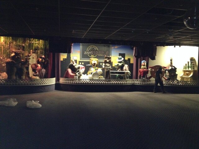
I have an animatronics show, similar to chuck e cheeses but its from an old arcade place in Michigan called Major Magics All Star Pizza Revue. Here is my application and problem:

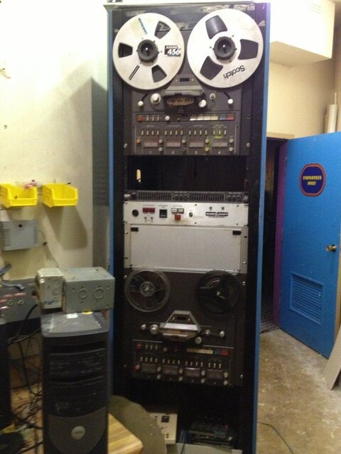
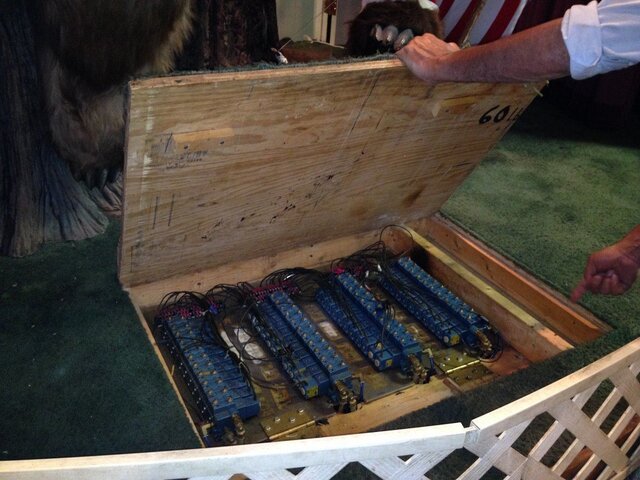
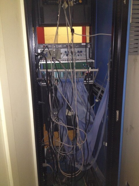
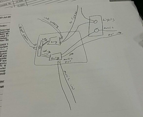
With respect to the animatronics show, I have an RA Gray control system that has a ton of ribbon cables coming off of it. Some cables control character movements (through mac valves) as well as lighting. Keep in mind this show was programmed back in 1982 and has a data steam that is coming from a laptop. The data stream goes from a laptop, into the control system and out to a ribbon cable. What it does is basically dims the showroom lights letting everyone know a show is coming on, stays dimmed while the animatronic show is playing and once the show is over, the lights go back to bright house lever. This is what I need to accomplish. I do not have the origial dimmer box.
So that's what I need to do.. have the ribbon cable feed into something 24VDC and have the output light up the lights in the ceiling 110vAC.

What would be the best, most cost efficient way to do this in 2015, explained in simple terms as I am not a Tekkie!

Thanks!
 
What you're describing screams for a relay. You might want something a little more heavy duty, but a quick search for Ice Cube Relay on Grainger shows plenty of options. A 24VDC coil with contacts rated for at least 120VAC is a pretty common configuration. That can take your 24VDC signal and control the light. If you need to dim the light rather than have just on/off control you'll need something more elegant which you could probably do with Gilderfluke's equipment.
What kind of control to you have of the existing system, can you make it supply the 24VDC signal or do you need to find a solution for that as well?


I have a pre programmed data stream that comes off my laptop, goes into the control system and out through a ribbon cable. I believe it an analog 0-10VDC signal. it comes on before the show, dimming the lights, keeping them dimmed during the show and lights back up and bright to house level once the animatronic show is over. What do you think is the best way to control the ceiling lights using this pre-programmed 24vDc signal?
 
I have a pre programmed data stream that comes off my laptop, goes into the control system and out through a ribbon cable. I believe it an analog 0-10VDC signal. it comes on before the show, dimming the lights, keeping them dimmed during the show and lights back up and bright to house level once the animatronic show is over. What do you think is the best way to control the ceiling lights using this pre-programmed 24vDc signal?


Actually All I have is one of those uce cube controls in a small home made box along with a similar relay thats function is to mute the showroom music so it doesnt interfere with the animatronic show music. I can email you a picture of my current box but I was under the impression that when we took the show down, we left some kind of dimmer box in the ceiling??? Im assuming this "ice cube" relay will only do a hard on or off of lights, no dimming? If I decided to go that route, how would it wire up in simple terms??
 

Attachments

  • IMG_5005.JPG
    IMG_5005.JPG
    200.6 KB · Views: 219
Post all the information you have on here. I am very interested to see what else makes this run.
 
The music is on the left channel, signals to lights and characters on right. Initially it played off a reel to reel but it's all now digital on a laptop.. It is fed into the control system and out through ribbon cables. The cables fire Mac valves for movements and solid state relays for on off of lights. It's all pre programmed, I have about 40 shows. 11 characters in the show, I still need help getting the lights , hopefully to dim or on-off
 
The music is on the left channel, signals to lights and characters on right. Initially it played off a reel to reel but it's all now digital on a laptop.. It is fed into the control system and out through ribbon cables. The cables fire Mac valves for movements and solid state relays for on off of lights. It's all pre programmed, I have about 40 shows. 11 characters in the show, I still need help getting the lights , hopefully to dim or on-off

pictures:
 

Attachments

  • IMG_2387.JPG
    IMG_2387.JPG
    99.9 KB · Views: 208
  • IMG_3665.JPG
    IMG_3665.JPG
    163.3 KB · Views: 214
  • IMG_3705.JPG
    IMG_3705.JPG
    102.9 KB · Views: 206
  • IMG_3713.JPG
    IMG_3713.JPG
    176.4 KB · Views: 188
  • IMG_3751.JPG
    IMG_3751.JPG
    126.5 KB · Views: 219
If I decided to go that route, how would it wire up in simple terms??

For hard on/off with the relay you'd wire the 24VDC signal to the positive side of the coil (most commonly labeled A1) with the negative side of the coil (usually A2) connected to the 0VDC. Then you would send the hot for the lights through one of the normally closed contacts. This way when your 24VDC signal goes high the coil will operate and disconnect the power to the lights. Whenever the 24VDC isn't holding the coil in then the normally closed contacts will pass the power onto your lights. The terminals for normally closed contacts are usually labeled with numbers that end in 1 & 2. For example 11 & 12 would be one normally closed contact and 21 & 22 could be a seconded one that is electrically isolated from the other contacts but still switches from the same coil.
 
I am having a bit of trouble understanding the 24vdc statement, but if your lighting control voltage is 0-10vdc, then there are many dimmers on the market that will run 120 volt lamps off a 0-10vdc control signal and do proportionate dimming. In fact, 0-10vcd was the analog control standard for the last 40 years. Many DMX dimmers (above shoebox grade) still have 0-10vdc inputs.

Start here-
http://www.leviton.com/OA_HTML/SectionDisplay.jsp?section=38394&minisite=10251
Leviton is one of many companies still producing 0-10 analog dimmer packs
 
Last edited:
I am having a bit of trouble understanding the 24vdc statement, but if your lighting control voltage is 0-10vdc, then there are many dimmers on the market that will run 120 volt lamps off a 0-10vdc control signal and do proportionate dimming. In fact, 0-10vcd was the analog control standard for the last 40 years. Many DMX dimmers (above shoebox grade) still have 0-10vdc inputs.

Start here-
http://www.leviton.com/OA_HTML/SectionDisplay.jsp?section=38394&minisite=10251
Leviton is one of many companies still producing 0-10 analog dimmer packs


How would I wire a solid state relay? The ice cube relay? If my drawing is incorrect, could you please revise... also where the solid states go...

Would it be wired like this?? (attached)Keep in mind it also shows the music "off" which cuts the music in the showroom durnin the show and kicks it back on when the show is over.
 

Attachments

  • IMG_5570.JPG
    IMG_5570.JPG
    43.2 KB · Views: 174
For any audio signal (music) you DO NOT want to use a SSR (solid state relay) due to the fact that they chop a bit of the waveform. This would produce noticeable distortion in the audio track. Use only a dry contact (mechanical) relay. An SSR can be used to control the lights but it is a on/off device so there would be no dimming.
Usually, SSR's have four terminals, two small and two large. The small ones are your control input. Make sure 24 volts are in the range of what the relay wants to see. It is not uncommon for an SSR to have a very wide range of acceptable voltages. The two large terminals are your output which would be put in series with the power feeding your lights.
Some SSR's contain two devices in the same package and have 4 input terminals and four outputs. They are exactly what you would expect, two units that happen to share the same physical case but are not interconnected.
 
I’m thinking the dimmers that were left behind were most likely an architectural/preset based control system that had two preset scenes. There are even lighting boards that can run scenes based on external switch contact closures. The relay was most likely triggering the dimming system between two preset scenes such as the full and dim scene. There are systems that can do this, however most are momentary contact inputs and not latched. I’m not what would happen if you used it in a latched setup, it may still work. Here is an example of one type of unit that will except switch inputs. http://www.lightronics.com/architectural_wallmount_dimmers_at402.html
You also said something about 0-10V analog output, however not sure where that comes into play as everything seems to go through relays.


Thanks for everyones help so far. Although I am STILL confused because I am not a lighting guy. Im still kind of hoping someone can explain the solution in easy terms. I also know this is the dimmer that they used to light and dim the showroom. (attached)
 

Attachments

  • Screen shot 2015-07-31 at 12.53.41 PM.png
    Screen shot 2015-07-31 at 12.53.41 PM.png
    45.6 KB · Views: 179
  • Screen shot 2015-10-07 at 12.57.36 PM.png
    Screen shot 2015-10-07 at 12.57.36 PM.png
    27.7 KB · Views: 160
  • Screen shot 2015-10-07 at 12.57.51 PM.png
    Screen shot 2015-10-07 at 12.57.51 PM.png
    32.2 KB · Views: 148
  • Screen shot 2015-10-07 at 12.57.58 PM.png
    Screen shot 2015-10-07 at 12.57.58 PM.png
    79.1 KB · Views: 146
There were 2 of these dimmers up in the ceiling somewhere that were left behind. (attached)
 

Attachments

  • Screen shot 2015-07-31 at 12.53.41 PM.png
    Screen shot 2015-07-31 at 12.53.41 PM.png
    45.6 KB · Views: 147
  • Screen shot 2015-10-07 at 12.57.36 PM.png
    Screen shot 2015-10-07 at 12.57.36 PM.png
    27.7 KB · Views: 144
  • Screen shot 2015-10-07 at 12.57.51 PM.png
    Screen shot 2015-10-07 at 12.57.51 PM.png
    32.2 KB · Views: 164
  • Screen shot 2015-10-07 at 12.57.58 PM.png
    Screen shot 2015-10-07 at 12.57.58 PM.png
    79.1 KB · Views: 137
The answer is in this sheet you provided. Where it says "Fade up, Fade down at the flick of a switch". The relay you have that is for lighting changes to closed which is tied into the control portion of this dimmer and tells it to run a scene inside the dimmer unit itself. Think of it as instead of someone manually pushing a start button, the relay does it for you which is automated.

I am no further along in solving my issue than I was 4 days ago when i posted. The guys on here talk in too technical terms for the average person to understand...so it just mumbo-jumbo. I even had my girlfriend read these comments as she is college educated and she just shook her head. Anyway thank you for your effort. I will have to seek answers elsewhere.
 
I also know this is the dimmer that they used to light and dim the showroom. (attached)

So, that dimmer is what you need. Go buy it. And, by that way, have it installed by a licensed electrician.

Much of the mumbo-jumbo in this thread has to do with confusion between your thread title, which says your control signal is 0-10v DC, and your first post, which indicates a 24v DC relay signal. Which of those two is your control system sending?


Sorry, did not mean to offend. i was simply stressing the fact I do not have an electrical degree nor am I a Super Tekkie.
if the dimmer box was available, I would buy it. They are not. i have asked/looked. Also the control system has a 24Vdc converter and I believe the signal the dims the lights is 0-10VDC. Sorry I was not clear on that sir.
 

Users who are viewing this thread

Back