I got to do a little deeper playing with a Barco FLM than I normally do, so figured I'd post some pictures.

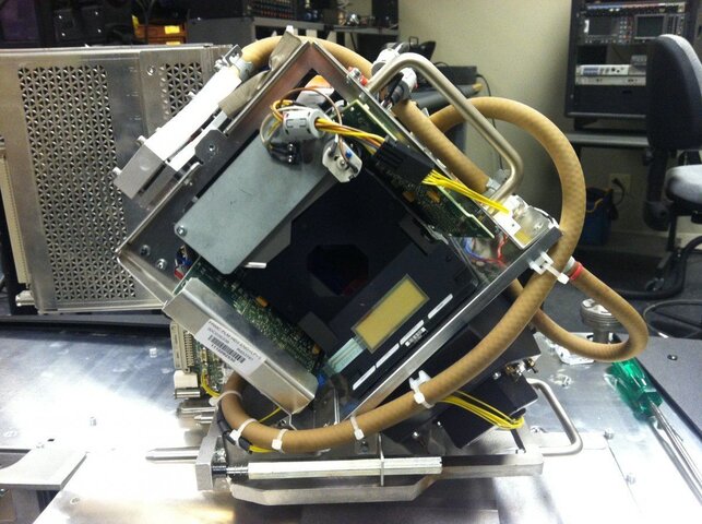
And this is what the optics on an FLM look like. I think I've posted some other pictures of them before, but I like this one because it shows the top of the light engine (side cover is a couple of quarter turn fasteners, it takes a bit more disassembly to get the top off). Short version of how this thing makes an image is a xenon lamp makes a whole lot of light which gets turned by a cold mirror (like many moving light reflectors are made out of). It then goes into the black tube called the light pipe where it becomes a even rectangular beam of light matching the DMD chips. It gets reflected by another mirror called the fold mirror (above and beteen the two yellow stickers, it's in a housing you can't see it) into the prism which is made up of 5 pieces. It is split into red, blue, and green, is sent to the correct DMD where it is either reflected to the lens or to the light trap on the top f the light engine. The light reflected to the lens is combined and makes the image. Yeah, it's a bit more complicated that that, but thats the short version. Feel free to ask if ou want more detailed explainations.

Yeah, it gets hot. Whats neat about this is you can see how the UV and IR light gets filtered out as it moves through the optic train. The bright red/white area is the light pipe which is the start of the light engine. The light blue is the fold mirror area. The blue lines are coolant hoses for the DMDs, light trap, and light pipe entrance.
And this is what the top of the light engine looks like on thermal. The hot spot is the light trap where everything that doesn't go out the lens goes. It would be hottest if projecting black and the coolest if projecting white (I think we had up a grey test pattern, so this is sort of medium). The light trap is also liquid cooled.

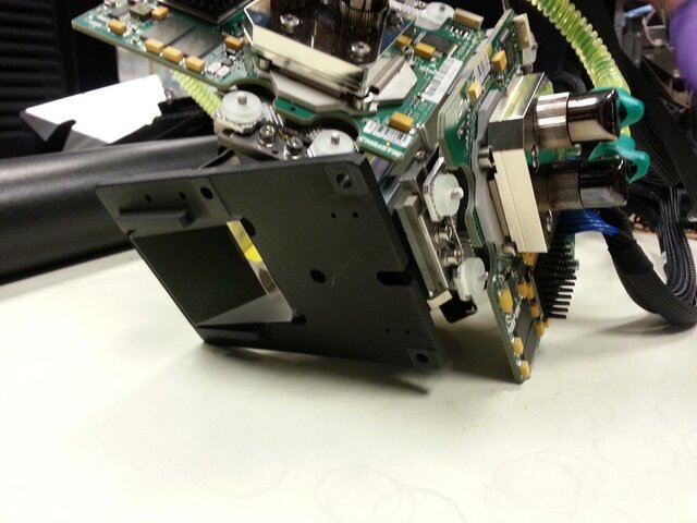
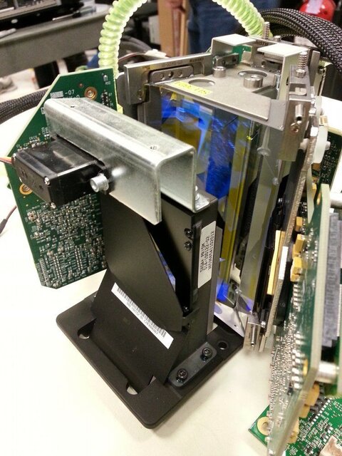
And thats what the light engine looks like (this is the back side). The multipin connectors go to the formatter interface board which controls the formatter boards the DMD chips are mounted on which actually control the DMD chip. Silver piece on top is the light trap. Thats the blue DMD in the center of the image.
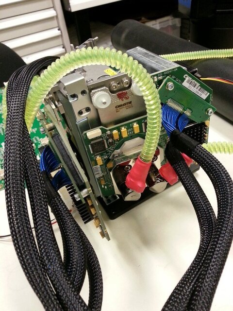
And from another view. Silver piece on the bottom left is the cooling block for the light pipe. The actual light pipe/integration rod is a roughly 11cm long piece of glass behind the opening in the black piece in the center of that cooling block. There would usually be a silver mask over the black mask but we'd already partially disassembled this before I thought about pictures. The light pipe is also way out of alignment in the picture. When properly aligned it's actually at an angle to the image that comes out the lens. That something I still struggle with when I'm working on one of these-- the image is not at all at the angles or direction it is when it comes out of the projector while it's traveling though the optics.
Hey, look what I found! Wonder what that is? Just kidding-- we knew it was there and that was one of the parts we were inspecting (you can't really see in the photo, but it was slightly hazy which means its bad). But the service documentation does not mention this set of relay lenses that sit between the light pipe and the fold mirror.
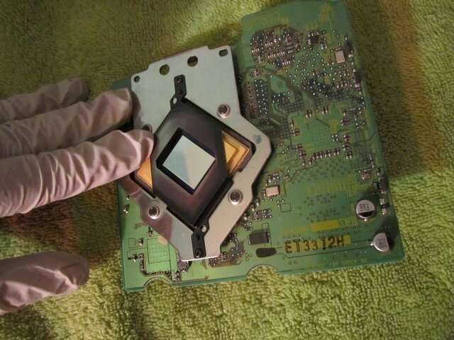
And heres a DMD chip. This one's actually from a different projector. You can see where the intense light burned the paint off surrounding the chip (there might have also been some misaligned optics contributing since it's mainly one side burned) which resulted in burned paint dust getting on the chip surface which shows up in the image. The FLM has sealed optics and the DMDs were fine, so didn't take that apart.

And this is what the optics on an FLM look like. I think I've posted some other pictures of them before, but I like this one because it shows the top of the light engine (side cover is a couple of quarter turn fasteners, it takes a bit more disassembly to get the top off). Short version of how this thing makes an image is a xenon lamp makes a whole lot of light which gets turned by a cold mirror (like many moving light reflectors are made out of). It then goes into the black tube called the light pipe where it becomes a even rectangular beam of light matching the DMD chips. It gets reflected by another mirror called the fold mirror (above and beteen the two yellow stickers, it's in a housing you can't see it) into the prism which is made up of 5 pieces. It is split into red, blue, and green, is sent to the correct DMD where it is either reflected to the lens or to the light trap on the top f the light engine. The light reflected to the lens is combined and makes the image. Yeah, it's a bit more complicated that that, but thats the short version. Feel free to ask if ou want more detailed explainations.

Yeah, it gets hot. Whats neat about this is you can see how the UV and IR light gets filtered out as it moves through the optic train. The bright red/white area is the light pipe which is the start of the light engine. The light blue is the fold mirror area. The blue lines are coolant hoses for the DMDs, light trap, and light pipe entrance.

And this is what the top of the light engine looks like on thermal. The hot spot is the light trap where everything that doesn't go out the lens goes. It would be hottest if projecting black and the coolest if projecting white (I think we had up a grey test pattern, so this is sort of medium). The light trap is also liquid cooled.

And thats what the light engine looks like (this is the back side). The multipin connectors go to the formatter interface board which controls the formatter boards the DMD chips are mounted on which actually control the DMD chip. Silver piece on top is the light trap. Thats the blue DMD in the center of the image.

And from another view. Silver piece on the bottom left is the cooling block for the light pipe. The actual light pipe/integration rod is a roughly 11cm long piece of glass behind the opening in the black piece in the center of that cooling block. There would usually be a silver mask over the black mask but we'd already partially disassembled this before I thought about pictures. The light pipe is also way out of alignment in the picture. When properly aligned it's actually at an angle to the image that comes out the lens. That something I still struggle with when I'm working on one of these-- the image is not at all at the angles or direction it is when it comes out of the projector while it's traveling though the optics.
.jpg")
Hey, look what I found! Wonder what that is? Just kidding-- we knew it was there and that was one of the parts we were inspecting (you can't really see in the photo, but it was slightly hazy which means its bad). But the service documentation does not mention this set of relay lenses that sit between the light pipe and the fold mirror.
.jpg")
And heres a DMD chip. This one's actually from a different projector. You can see where the intense light burned the paint off surrounding the chip (there might have also been some misaligned optics contributing since it's mainly one side burned) which resulted in burned paint dust getting on the chip surface which shows up in the image. The FLM has sealed optics and the DMDs were fine, so didn't take that apart.