Interesting little electrical fire this morning

JD

Well-Known Member
Not directly related to lighting, but the same physics applies. Got a "no heat" call from a friend who has a heat pump. System was electrically dead. I figured it was an open 25 volt transformer. What I found was surprising! Layout- Unit runs off a double 50 amp breaker. Wiring to the air handler is #6 (electric heat backup) Inside the unit, these wires are wire-nutted to the internal wiring which is #10. The #10 then goes to a cheesy little spade crimp which connects to a thermal limit switch on the electric heat unit. So what failed? The wire-nuts! BOTH were burned to the point where the wire snapped off one and no plastic was left on either. Examining the crispy remains, the wires appeared to be fully seated and the spiral was tight on them. Now, I've seen those spade lugs go, but they were fine. No sign of heating on the #10. A few inches back both were shiny copper when stripped. Wire-nuts! We don't think twice about them!
 
All I can think is perhaps the #10 wires were either tinned or oxidized. Is the #6 wire solid and the #10 stranded?


Sent from my iPhone using Tapatalk - now Free
 
Sorry about the damaged post above. Both were stranded and straight copper (no plating.) Pic below. Although the black wire burned off, there is still copper from it in the wirenut spirel. The home owner tells me she had been smelling this for years, and from what I can tell,
the unit is at least 20 years old.

damaged_wires.jpg
 
In my own opinion, this is something @STEVETERRY might want to look at. My conclusion is the stage was set for this at the time of installation. The culprit, I think, is the disparity of strand size between the #10 with fine stranding, and the #6 with coarse stranding. The manufacturer sells the unit with the #10 pigtails, and a 50 amp draw requires the use of #6 to feed it. Crank a wire-nut down on such a disparity of strand size, any you are going to damage a lot of the #10 strands. To me, a better interface would be a terminal strip or lug block as would be found in a dryer or electric range. That way the strands are not mixed.
 
I replaced this nasty mess at a friend's 90 year old mother's house a few years ago. When she bought the house a big plus for her was the first floor laundry. Trouble was the idiots who built it ran the 120v washer receptacle off one side of the 220v dryer receptacle. It took a crow bar to separate the two pieces........luckily no fire resulted from this one.
PICT0038.JPG
 
In my own opinion, this is something @STEVETERRY might want to look at. My conclusion is the stage was set for this at the time of installation. The culprit, I think, is the disparity of strand size between the #10 with fine stranding, and the #6 with coarse stranding. The manufacturer sells the unit with the #10 pigtails, and a 50 amp draw requires the use of #6 to feed it. Crank a wire-nut down on such a disparity of strand size, any you are going to damage a lot of the #10 strands. To me, a better interface would be a terminal strip or lug block as would be found in a dryer or electric range. That way the strands are not mixed.

JD--

I totally agree with you. i looked at the listings of various wire nuts and they are quite specific as to allowable combinations of wire gauges, strandings, and types.

Also, my radar gets illuminated any time there is a transition between wire gauges (#6 to # 10 in this case) without overcurrent protection for the smalller gauge.

ST
 
It's hard to tell from your photo, but if one wire is Aluminum and one is copper, a contact paste for these dissimilar metals could have helped prevent this. Split-bolt wire nuts are also notorious for trouble, and last week I found one that had caused a fire that should have never been (another story).
 
No. All copper. IMHO, the manufacturer should have supplied an input terminal block as compared to #10 pigtails. (Especially considering it's near 40 amp draw and recommended 50 amp circuit.) That is how it is done in most electric ranges, dryers, and every dimmer pack I've ever connected. The problem is, mounting one in there would be considered to be modifying the appliance, which would put it outside it's UL listing. I avoid split-bolt bugs so what does that leave? Well, in-line reduction lugs ( http://www.homedepot.com/p/Blackbur...ire-Stop-ASR2506-B1-10/100190266?N=5yc1vZbm6y ) covered in friction tape or heat shrink tubing? The old install sheet that was in the unit showed wire-nuts, but as was explored before, I am still uncomfortable with that due to the disparity between gauges. For fun, I opened up two other units, one there and one at a neighbor's. Both were done with wire-nuts.
I have subsequently talked to a friend in HVAC, who commented "yea, that's how they all are." Although contained inside a metal cabinet, I still wonder the failure rate.

 
Seen it before and will see it again. And yes things like that are typically done with wire-nuts. Unfortunately the manufacturer is not going to supply nice terminal block connections (or such) which personally I think is stupid. They do for most air-conditoners, even the smaller ones (well usually still using a wire-nut on one of the two wires).
Every one I've ever installed has been done with wire-nuts.

A crimped butt-splice would be no good in my opinion for two main reasons: 1, different wire sizes, 2, solid wire vs stranded wire, not to mention the wire sizes are #10 and #6.

A screw connection such as a splice or terminal block would be better. But as mentioned the manufacturer is not going to spend the extra money on that. Besides the connection is inside of an ISOLATED proper junction box, so if the connection fails there is no problem... Cut it off and re-connect. Unfortunately that is the reality. Unless you want to install a terminal block?
 
In the electrical trade Polaris taps are a common solution to that problem. Pricey but they do the job quite well.


proxy.php
 
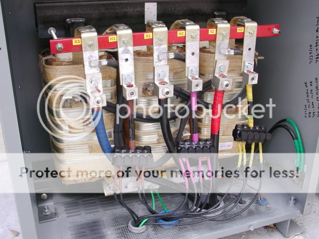
Looks like a Wye transformer in Delta service. Looking at the bottom strap, it appears tied to secondary on all three cores, but is then only tied to ground (no neutral), so basically, a non-floating Delta output. For a while (at least in this area) large buildings were wired 480 and then had step downs for local service in various areas. They looked the same way, except the neutral was in use. I guess if it were feeding HVAC the neutral may not be in use. If multiple transformers were in use, the primary would be looped like that from box-to-box. The two conduits on the hi-side appear to be such a looping, but it appears smaller conductors were paralleled. Not sure what country this pic is from, but here in the US you can't parallel conductors that small.

EDIT: Why, I'll be darned! Was googling something else and ran across the picture and forum chat about it!
here- http://forums.mikeholt.com/showthread.php?t=125622
 
What threw me was the purple, rather than orange for 480V, facetape (phase tape).

Lots of purple in PA. Orange is used for the high-leg or "wild phase" on a center tapped delta. (120-120-208) On 480, purple is used instead of orange. A lot of old services in commercial buildings use high-leg delta as most of the demand is for HVAC. The remaining center tapped leg (black - white - red) provides 120-0-120 / 240 for whatever office and outlets are needed. I'm not sure any new services are being done this way. Almost every modern building I have been in has been 120/208 Wye (Black - Red - Blue - White). Only see tapped delta in legacy buildings.
 

Users who are viewing this thread

Back