Why do we need to have the gains bottomed out?

your misconception is you considering it volume after amplification, this is not the case its volume before amplification, its the incoming signal being adjusted not the signal leaving the amp.
 
Alright, sorry maybe I did not understand that the volume on the amp controls the input not output. But either way. My only problem was because the amp volume was nearly off..and the amp treble was all the way up.. That's why it would squeal so quickly.
Our amp is back stage, not near the control area. So I did not notice this until I went back there.
 
Ah highschool theatre ; )
Thinking of cutting some semi circle in the amp rack backstage to put the cables through and still lock the cabinet.

And painting Do Not Block signs on the floor in a rectangle around the breakers, dimmer rack and amp rack so I am not climbing over mountains of sets.. And maybe also under the ends of the light bars. Yesterday I am trying to lower a light bar and it isn't going down, Im like "wtf.." Only to see a big wall in the way of the bar on the other side of the stage.
 
...And painting Do Not Block signs on the floor in a rectangle around the breakers, dimmer rack and amp rack so I am not climbing over mountains of sets. ...

I'm with you on this one! Perhaps some of these signs also?
proxy.php

Electrical Panel Signs ? Keep Operating Environment Safe with Danger Signs , SKU: S-0645
Of course, for it to have an effect and be enforced, the directive will have to originate from an administrator, not a student.

SIDENOTE:
While googling, I found this site: La Mesa, CA - Official Website - Fire Safety Checklist for Schools
Without reading the URL carefully, I thought it said "www. City of Flames a .com":oops:
Contains very useful guidelines pertaining to the California Fire Code (your state's may vary), including:

30 inches of clearance shall be provided in front of electrical panels. Do not tape circuit breakers in the open position, cover electrical panels with any material or obstruct in any manner. (CFC 605.3)
 
Oh, nice. Haha, we have a storage closest that people like to go into, Maybe I will put a similar sign on the door :twisted:
And yeah those signs would be helpful too, The other day I was going to turn the amp off and I was walking on a mattress, boing, boing.
I love intimidating signs :D
 
Oh, nice. Haha, we have a storage closest that people like to go into, Maybe I will put a similar sign on the door :twisted:
And yeah those signs would be helpful too, The other day I was going to turn the amp off and I was walking on a mattress, boing, boing.
I love intimidating signs :D
It's not an intimidating sign, it is simply stating a code requirement. I would be cautious about intentionally misapplying such signs, it could be a red flag to an inspector. It might be better to use more vague language in those situations.
 
Yeah, I guess I just need to keep it locked up more often.

So it is 32 inches in front of electrical boxes right? Dont want to put up a false sign.
All our breakers and the dimmer rack is in a corner.
 
So it is 32 inches in front of electrical boxes right? Dont want to put up a false sign.
All our breakers and the dimmer rack is in a corner.
Check your local electrical and fire codes. Each jurisdiction will be a little different. For example, in British Columbia, it is 1 Meter of clear space (39 1/3 inches).
 
Last edited:
Sharyn, Yeah if I do anything I will be doing that. And I also mentioned probably making a somewhat small rectangle below the edges of the electrics. I was bringing one down the other day and it stopped, was like "Did the power tubing get caught?" so when I am at the other side of the stage Is ee a wall with the end of the electric resting on top. Five minutes of moving that thign and I was back to replacing lamps.
Going to have take a trip to the art room and borrow some paint and stencils :p
 
:eh: I think what you've missed is this:

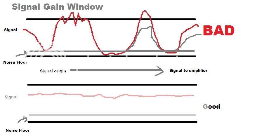
Every device in the chain from signal origin to the amplifier has the ability to boost or attenuate the signal. As has already been stated (somewhere in this thread), you want to keep your signal at a level so that it is well above the noise floor, but not so high that it clips. See picture...

proxy.php


This is what people were trying to convey to you.
 
I think what you are showing here is the result of compression.....increasing or reducing gain will not affect the dynamic signature and relationships of a complex waveform (compress) until you reach the limits of a systems headroom. When that occurs, the waveform is not compressed but clipped at the peaks, resulting in harmonic distortion (never to be confused with compression).

Your written description is correct, your diagram is misleading.

:eh: I think what you've missed is this:

Every device in the chain from signal origin to the amplifier has the ability to boost or attenuate the signal. As has already been stated (somewhere in this thread), you want to keep your signal at a level so that it is well above the noise floor, but not so high that it clips. See picture...

proxy.php


This is what people were trying to convey to you.
 
I'm not sure what the lower black line is but I took the upper black line to be the maximum signal level, or the clip level, and the idea being to show that you want your signal between that maximum and the noise floor. I think the difference may be that it appears the intent was for the diagram to reflect the path through the, you are not seeing the signal waveform but rather the signal level at different points in the system. Perhaps more like the signal level diagram at the bottom of http://www.yamahaproaudio.com/products/mixers/mg32_24/pdf/MG32_14FX_block_level_diagram.pdf.

In that case it makes the point but is very simplified compared to a real system where the you may have the equipment noise floor and maximum level varying at different points and multiple steps of gain and attenuation affecting both the noise floor and the signal level.
 
I see now. Man, that confused me big time. Since I was not seeing anything along the horizontal to signify gain stages or components, I thought I was looking at waveform.

I'm not sure what the lower black line is but I took the upper black line to be the maximum signal level, or the clip level, and the idea being to show that you want your signal between that maximum and the noise floor. I think the difference may be that it appears the intent was for the diagram to reflect the path through the, you are not seeing the signal waveform but rather the signal level at different points in the system. Perhaps more like the signal level diagram at the bottom of http://www.yamahaproaudio.com/products/mixers/mg32_24/pdf/MG32_14FX_block_level_diagram.pdf.

In that case it makes the point but is very simplified compared to a real system where the you may have the equipment noise floor and maximum level varying at different points and multiple steps of gain and attenuation affecting both the noise floor and the signal level.
 

Users who are viewing this thread

Back