Understanding Touring Dimmer Rack Patch Panels

I know that we're seeing them phased out in the installation market, but I still have 8x 48 channel dimmer racks in my rental inventory with full patch panels that see regular use. They won't go out of style in the temporary market until we've shifted completely out of dimmers, or made the downgrade to dimmers at the fixtures.

I'd argue they're still a pretty important thing to know about, even if you don't totally understand how they work.
 
See here: https://www.controlbooth.com/threads/etc-sensor-patch-bay-touring-rack.40366/ .

At the fixture, a light is plugged into one of six circuits on the multi-cable break-out. Let's say the second circuit.
The break-out is then plugged into a Socapex-style multi-cable that happens to be labeled [R1]A.
At dimmer Rack#1, the male end of the soco is plugged into outlet labeled A.
Inside the rack's patchbay, circuit A2's single banana-type plug is inserted into Dimmer#1.
At the console, dimmer#1 is soft-patched to control channel#1.
Bring up channel 1 to full, DMX tells the CEM to bring up dimmer 1 to full.
Electricity flows from the dimmer via the circuit to the luminaire.

Notes:
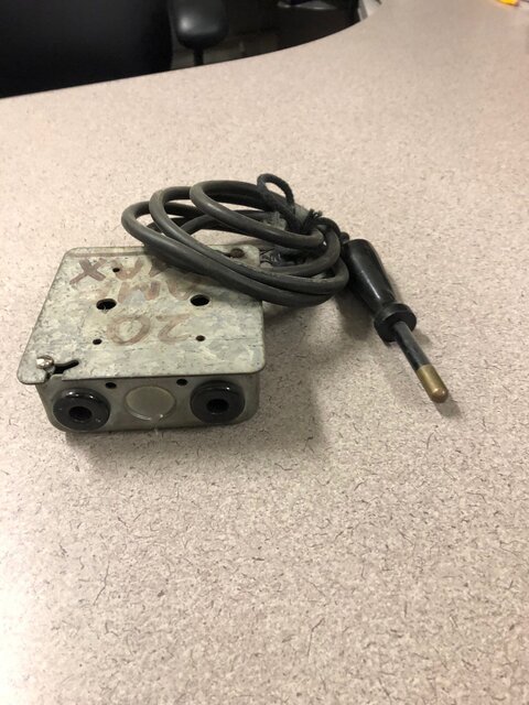
The hanging cords are the hot conductor s of the circuit s and the jacks are the dimmer outputs.
The pin patch only carries the hot wire; all the neutrals are bussed together inside the rack.
Only the Socapex outlets are patchable. The 2P&G receptacles on the rack are direct to dimmer.

Any questions?

Good explanation. But some may also look for an answer to WHY a touring rack with 20A branch circuits and 20A dimmers needs a patch panel? After all, permanent installation patch panels were used to connect small numbers of BIG dimmers (3.6kW to 12kW) to larger numbers of 20A branch circuits. In a high density 2.4kW touring rack, why not simply hard wire the Socapex circuits to dimmer outputs in a dimmer-per-circuit arrangement?

As the guy who designed and built the first 96-channel digital touring dimmer rack in the industry at Production Arts in 1983, I can offer an explanation to this:

1. A touring rack without a patch panel is wasteful of both circuits and dimmers. The original high-density touring rack had sixteen 12-circuit multicable outlets. If you sent a multi to a location that needed less than 12 circuits (say a box boom), without a patch panel you would be forced to use up 12 dimmers. The same holds true, to a lesser degree, with 6-circuit multicables.

2. A patch panel was needed to twofer circuits at different locations, which was common in many hookups.

BTW, that patch panel topology and output circuit count persists today in modern touring racks, so I guess it might have been on the right track.

But, as I'm fond of saying, in ten years we may struggle to remember what a dimmer was. :)

There you have it.

ST
 
Another use for patch panels is balancing loads across all three phases, as well as reassigning individual circuits to hot patches or relay cards as needed out on electrics.
 
Then there were the Kliegl patch options:
ROTOLECTOR
Then there was the SafePatch telephone exchange style unit. Unlike the Century one shown above the Kliegl had either a toggle switch or perhaps a circuit breaker mounted below or beside each hole. If you were unpatching a circuit when you pulled out the plug it tripped the switch off. When patching you inserted the plug and flipped the switch back on(it could be done one handed).
SAFEPATCH

Rudder Auditorium at Texas A&M University had a Kliegl patch panel very similar to the SAFEPATCH, just without the circuit breakers. It was fed by (60) 10k? dimmers and had 400+ circuits. Each dimmer had 10 holes and all the circuit hots were above with counter-weighted, retracting leads. It was an impressive site and fun to patch and re-patch for shows. It was still in service when I graduated in 2005, but now their tech spec packet indicates (6) 96 ckt Sensor racks.
 
Good explanation. But some may also look for an answer to WHY a touring rack with 20A branch circuits and 20A dimmers needs a patch panel?

But, as I'm fond of saying, in ten years we may struggle to remember what a dimmer was. :)

There you have it.

ST

Great write up Steve, made me recall and not so fondly, that 12 circuit multi.....

And for those occasions and on a house patch panel, when there was excess capacity on the dimmer and you had 1 too many patch cords to plug in, we had these. I've posted this before and there were a few who questioned the code compliance of this.
 

Attachments

  • Patch Panel Two-fer.jpg
    Patch Panel Two-fer.jpg
    415.7 KB · Views: 304
made me recall and not so fondly, that 12 circuit multi...
I've never met anyone who remembers 12/37 Pyle-National cable "fondly."

And for those occasions and on a house patch panel, when there was excess capacity on the dimmer and you had 1 too many patch cords to plug in, we had these.
Rumor has it "patch panel two-fers" exist for Sensor touring racks also. As well as long extensions to jump from one rack to another. Since 1992, I've never seen either in use.
 
I've never met anyone who remembers 12/37 Pyle-National cable "fondly."

Rumor has it "patch panel two-fers" exist for Sensor touring racks also. As well as long extensions to jump from one rack to another. Since 1992, I've never seen either in use.
@derekleffew and @SteveB In the 1970's we had 6Kw / 50 Amp patch panel quad boxes housing four 100 Amp females with each box fed by approximately 6' of 6 gauge copper cable sourced by a 100 Amp patch panel male connector. in 1973 when the venue opened, we borrowed several of these quad boxes from Toronto's O'Keefe Centre. By approximately 1975 we punched additional holes in the vertical face of our patch panel and added 18 four-way and five-way patch panel plugging boxes within our patch panel each with counter-weighted 6 gauge copper tails and 100 Amp male patch panel connectors.
Pyle National 12 / 37 12 circuit 20 Amp cables and connectors. When I left my theatre gig and played head electrician in an automation and scenery shop for a few years beginning in 1991, the first major project we built was a flown incandescent and neon sign for "Best Little Whorehouse Goes Public"; directed by Tommy Tune with lighting design by Jules Fischer and Ms. Peggy Eisenauer; the sign was fed by six Pyle National's from one side plus five more Pyle Nationals from the other side and one Socapex for a total of 138 twenty Amp circuits including two spares; one spare in one of the Pyle Nationals and the remaining spare in the lone Socapex. I've posted of this sign in greater detail here on the Control Booth forum before, possibly twice.
Toodleoo!
Ron Hebbard

Patch panel quad boxes. That’s not something I ever want to see. I thought my two-fers were bad enough.
 
Patch panel quad boxes. That’s not something I ever want to see. I thought my two-fers were bad enough.
@SteveB The original telco-style patch was custom built by Strand Century in their Toronto, Ontario shop. All of the female receptacles were rated for 100 Amps / 12 Kw. All of the male connectors were rated for 100 Amps / 12 Kw. All one hundred of the dimmers were 6 kw each. Unfortunately each of the six non dims were only rated at 20 Amps. Originally there were 307 20 Amp load tails each protected by a 20 Amp Heinemann magnetic breaker and 17 50 Amp load tails each protected by a 50 Amp magnetic breaker. The panel was approximately 7.5 feet wide with the pairs of female receptacles repeating three times across the width of the panel thus there were six receptacles per 6 Kw dimmer with two near the left end, two more near the center and the last two towards the right hand end thus if you wanted to patch six FOH load circutis into one 6 Kw dimmer you could make two reach for sure and possibly two more may reach the center two females but there was no way your last two FOH load tails would reach all the way across to the last two receptacles near the right hand end. This was why we needed the quad boxes to manage to plug six tails into a six Kw. dimmer. Lamps were typically 750T12's and 1MT12 1 Kw's so plugging six per 6 Kw dimmer was never a problem with the 750 Watt lamps. I suspect I've more than beaten this to death.
Toodleoo!
Ron Hebbard
 
Last edited:
After watching almost a week's worth of patch systems descriptions I decided it's time to throw this one into the mix.

In the early '60s I worked as chief elec. in a small theatre in Cleveland. The plant was built in the late '40s and apparently was designed (or at least assisted by) a very good theatre designer. About three hundred capacity, 30 foot prosc., 40' to back wall, 20' off both SL & SR, (sorry, no orch. pit :-( ), TWO very nice ceiling coves the full width of the house, nice hidden prosc. splay positions, grid over twice prosc. height. The board was in a projection booth with good stage visual; 48, 6 kW autotransformers plus some for the house. The board and cross-connect were built by Cleveland Switchboard Co., a local manufacturer who we used many times to build oddball stuff for various projects.

Now, to the patch panel. On the back wall of the booth was a cabinet about 8' high x 6' wide and a foot deep. In the cabinet was a slate back board with 48, 6' vertical copper buss bars, each about 1" x 1/8", one for each dimmer circuit, with a 60A cartridge fuse at the top of the cabinet for each bar. The bars were mounted perpendicular to the back board with the 1/8" edge facing edge out. Mounted above (away from the back board) in front of these vertical bars were horizontal bus bars for each circuit (I don't remember how many; this has been a few weeks ago but they filled the 7' cabinet), also 1" x 1/8" with the1/8" edge facing out. Each horizontal bar had a 30A cartridge fuse for its circuit at the side of the cabinet. On each horizontal bar was a plug (for want of a better word) which could be moved side-to-side when pulled "out" away from the back board without touching the vertical bars below. The plug for any circuit could be pushed "in" to make contact with the vertical bus bar for any dimmer.

This cross-connect allowed any circuit to be connected to any dimmer. Of course,this operating cross-connect this required a bit of intelligence (read: a NON-IDIOT) on the part of the electrician. One COULD plug everything in the theatre to ONE dimmer, but this would be kinda stupid and would instantly blow the dimmer's fuse. One COULD plug, kill and re-plug hings "hot", but this also would be kinda stupid and hard on the buss bars. One COULD lean up against the cross-connect and get a big surprise, but this also would be kinda stupid. One COULD reach into the cross connect and grab things while hot, -- but then, well, you know.

I never had any trouble plugging shows per the designer's wishes, sometimes re-plugging things pretty quickly between dim-outs & dim-ins) (Thanks, Paul Marantz!) and never heard of anyone getting zapped on this equipment. Oh, and this was long before OSHA and everything else that interferes with our lives.
 
Hey, I just want to throw out a huge thanks/appreciation to all of the industry veterans who’ve taken time to comment on the history of the patch panel and similar technologies, here.

The textbooks I’m studying as I try to rebuild my foundation in lighting don’t even scrape the surface on the evolution of the technology over the years, and I imagine a certain level of appreciation for that evolution is lost with modernization and ignorance.

I can’t thank you all enough for giving me a solid hour of reading material, and enough reference to spend another week just googling history.

I hope you don’t all expect to land on my USITT “IOU Beer” tab though; I don’t think I can afford all that booze. Will internet high fives suffice?
 
@RonHebbard asked me to post this picture in this thread for him.
patch_panel.JPG


RonHebbard said:
The photo is of a slide patch currently still in use in Hamilton, Ontario, Canada. Odd numbered load breakers are across the top and even numbered load breakers are across the bottom. It was originally installed in a secondary school theatre in 1970 and relocated to a community theatre approximately 20 years ago when a larger slide patch was installed in the secondary school.

Toodleoo!
Ron Hebbard
 
@RonHebbard asked me to post this picture in this thread for him.
View attachment 17604
@NateTheRiddler When the slide patch was originally installed in 1970 it distributed 42 Six Kw dimmers and six non-dims to approximately 98 or 100 twenty amp old style twist locks. In its current use I believe it's distributing 36 2.4 Kw CD80 Pack dimmers plus 6 non-dims; one or two of the non-dims power a smaller DMX shoe-box dimmer typically utilized to dim practicals.
Thanks @dvsDave for posting this photo.
Toodleoo!
Ron Hebbard
 
@RonHebbard asked me to post this picture in this thread for him.
View attachment 17604
Awesome thanks Dave and Ron!

I remember when I started at the Grand the McManus had a slide patch... However, some people in the past obviously did some patching live and/or other improper operation causing it to stop working correctly. Was ripped out and dimmer rack replaced when the Strand a21 architectural panels were installed. Wish I had taken photos back in the day!
 
@RonHebbard asked me to post this picture in this thread for him.
View attachment 17604

I find it remarkable that it was found to be cost effective to re-locate this in 1999 or there-abouts. The labor to remove and re-install boggles the mind. This is likely a good 15 years AFTER dimmer-per-circuit systems were the cost effective system.

But when you say "community theater" the image that comes to mind is somebody's Dad/Husband/day-job-is-an-electrician donating some time.
@SteveB You're conjuring the right image: The three Strand CD80 twelve by 2.4 Kw packs are in the basement in a locked room off the prop room to isolate their fan noise. 1.25" EMT brings the dimmer outputs straight up the wall to the bottom of the slide-patch and the approximately 100 circuits are distributed around the theatre / auditorium as several Socapex's and primarily 2P&G's as tails off of troughs. Fixtures are a totally mixed bag from ancient ellpsoidals still running a very few 500T14bi-posts to Strand 2200 series, Altman 65's and their predecessors, plus Strand grey ellipsoidals that pre-dated the 2200 series to Source Four 36 and 50 degrees. Add a pair of I-Mirrors and stir to suit. The community theatre has been in operation since sometime prior to 1900 with only a minor interruption for the first world war. The person largely responsible for keeping everything maintained and operational is retired from his career as a sales support technologist with Reliance Electric specializing in LARGE AC and DC motors and drives globally; think steel mills, pipe lines and ocean port gantry crane control systems and their drives.
Toodleoo!
Ron Hebbard
 

Users who are viewing this thread

Back