Clamp Meters

Diarmuid

Active Member
I've had a question hanging around in the back of my head for quite a while...

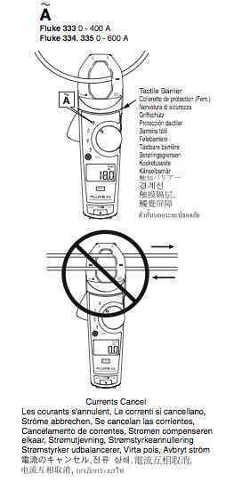
My understanding of a clamp meter, is that you just take a cable, put the cable in between the jaws of the clamp and then it tells you the current going through the cable,and dependent upon how good the clamp meter is, it tells you the voltage etc.

Is that right?

The reason for all this confusion, is that we have a clamp meter at school, and when we clamp it around a cable, it doesn't work... and the rather ambiguous instructions don't say whether they refer to a complete cable, or just one conductor of that, as in a live wire...

It might just be that our clamp meter is dodgy, but I thought I'd make sure, before I get one in the post christmas sales..

Thanks for your help!
 
First, the clamp meter must be used only around a single wire conductor, not around cable. Second, the clamp meter will only tell you amperage, not voltage, without physical contact using the included probes. Disclaimer: Always use every available precaution when working around live electrical circuits! Here's the one I use, Fluke 30--it's not the best, but adequate for my purposes. It has been replaced by the Fluke 333A, MSRP $149.95 US.

Sounds like yours is not a very good manual. Out of curiosity, what make and model is your meter? Here is a link to the manual for the Fluke 333. It will probably help clear up your confusion.
 

Attachments

  • clamp_meter.jpg
    clamp_meter.jpg
    18.8 KB · Views: 362
Last edited:
First, the clamp meter must be used only around a single wire conductor, not around cable. Second, the clamp meter will only tell you amperage, not voltage, without physical contact using the included probes. .

I believe an Amp meter, as a clamp around a single HOT conductor meter is called, will only do a reliable test on loads whose sine wave is not distorted in some fashion - I.E. they don't work to get you the load of a Sensor 96 dimmer rack (or any dimmer rack, for that matter).

Or am I thinking of something else ?.

Steve B.
 
I certainly hope you are mistaken, SteveB, as I've used my Fluke 30 to measure amperage loads on many touring dimmer racks and ML Distros, and never been challenged on the results. I think you may be confused on the measurement of output voltage of a given dimmer, for which you need a "true RMS" (Root Mean Square) meter.
 
I'm not sure the make and model of ours, because it is at school, but I'll try and find out...

And if it can only be clamped around the live conductor, would I be right to suggest that in most applications it can't be much use? I guess if you had like a 3 phase system, with all the different phases on seperate inputs, then it would be ok... but as it can't be used for actual cables, for installed systems and such, it can't be used very effectivley?

Thanks for the help.
 
Clamp meters do have practical limitations in getting to the single conductor which generally involves getting close to live wires, a clamp on meter loses accuracy on dimmed settings as the waveforms become too complex to analyze accurately and they do not read the dc content of the waveform, but they are near enough for all practical purposes.There are cheap rms meters on the market which are perfectly useful for the type of work we do.
 
I'm not sure the make and model of ours, because it is at school, but I'll try and find out...
And if it can only be clamped around the live conductor, would I be right to suggest that in most applications it can't be much use? I guess if you had like a 3 phase system, with all the different phases on seperate inputs, then it would be ok... but as it can't be used for actual cables, for installed systems and such, it can't be used very effectivley?
Thanks for the help.

If you want to measure the current in a single-phase, two wire plus ground branch circuit or feeder, just make yourself a male-female adaptor with the outer jacket of the cable removed so that you can get the clamp around the insulated hot or neutral conductor.

BTW, the clamp meter does not care if it's measuring the neutral or hot conductor--the current is the same in both for a single-phase circuit.

For higher current feeder applications where you may be clamping around live conductors on equipment with the covers off, you are now under the rules of NFPA 70E "Standard for Electrical Safety in the Workplace" in North America. This defines the protective gear you must wear, and the various boundaries and voltages where different rules apply. DO NOT ATTEMPT THIS without training and expert help!

Of course, this does not apply if you are clamping around insulated, single conductor feeder cables or branch circuit conductors outside equipment or switchgear.

ST
 
If you want to measure the current in a single-phase, two wire plus ground branch circuit or feeder, just make yourself a male-female adaptor with the outer jacket of the cable removed so that you can get the clamp around the insulated hot or neutral conductor...

Would I be right to assume that removing the insulation from a cable, to just leave the insulation on the wires, wouldn't be possible to do in a way that would pass electrical safety testing? Basically would it be safe to do it, or could it be put through a junction box or something like that to make it safer?

Thanks
 
Would I be right to assume that removing the insulation from a cable, to just leave the insulation on the wires, wouldn't be possible to do in a way that would pass electrical safety testing? Basically would it be safe to do it, or could it be put through a junction box or something like that to make it safer?
Thanks

There's no need or purpose in removing any insulation. A clamp around Amp-meter will measure the current with insulation intact. It's measuring the EMF.

As further clarification, the typical clamp around amperage measuring meter - here's a photo of an Amp-Probe model, has a set of jaws that open to allow you to wrap the jaws around an insulated conductor, the jaws then close to create a loop around the conductor. There's usually a few inches of clearance between the conductors and the insulated jaws of the meter. Care and attention needs to be in place to do this measuring safely and Steve T. has listed a link as to the methods now required.

As to usage. One typical example would be attempting to get a rough measurement of the normal load on an electrical panel that has space(s) for additional breakers, but whose existing loading is undetermined. Removing the panel cover and testing the hot legs, presumably while the loading is as close to maximum current usage, would then yield a reading.

SB
 
Last edited:
To Steve Terry

By the way - a Merry Christmas to all you folks at ETC !.

A question arose as to whether a clamping amp-probe will accurately measure a dimmed load ?. Does the distorted sine-wave affect the readings ?. That's what I was told years ago and is why I stopped using my personal Amp-Probe to measure portable dimming systems.

Steve B.
 
I wasn't refering to removing the insulation from the induvidual wires, just removing it from the cables, so as to make a jumper, like the one SteveT mentioned above, allowing me to measure the current draw of a single phase cable. Because otherwise, it would only be used for about one job a year, in which case I could spend the money better elsewhere.
 
Most, if not all "amp-probes" will not give you a true reading on distorted waveforms, but will give you a pretty accurate idea of the thermal load on the cable. For instance, clamp it on a non-power factored 100w HPS ballast and you will read about 2 amps. Connect the power factoring capacitor in the ballast, and watch as the meter drops to 0.9 amps. Same power going to the lamp, but as we know, non-power factored ballasts will heat the wiring up more than those with power factoring. (please don't try this if you arte not trained, don't want any deaths on my conscious at Christmas!) So, the end result is the amp-probe will give you a good ballpark figure about how the wire feels about it's loading.
 
One time my amprobe proved invaluable: I had a 50gallon trash can full of unlabeled PAR64 lamps, a mixture of 500W and 1000W. The manufacturers' printing was either faded or worn off. I did as STEVETERRY suggested and made an Edison to 2P&G adaptor, using the Blk,Wht,Grn inner wires from a 2' piece of 12/3 SOOW. Clamped around the hot or neutral wire, when the meter read 8.3A or so, I knew I had a 1000W; when it was just was over 4.0, I knew I had a 500W. I could ascertain by looking whether it was WFL, MFL, or NSP. After testing each lamp, I wrote "1K MFL" or "500 NSP" or whatever on the ceramic with black Sharpie™. Since then I've always written on the ceramic as soon as I open a new PAR64 lamp box.
 
Last edited:
For GE 4552 and 4559s, there's no ceramic, so I've had to write on the glass, but that burns/wears off over time. Every place I've worked seems to have had a mixture of 4552 and 4559, never on the same bar, of course.:)

ship and len are probably too young to remember HiLights, a major R&R company of the '70s and '80s. I bought all their PAR lamps when they finally folded. They had engraved "HLI" in the back of every lamp, with an electric engraver. Taking it a tad too far, if you ask me.
 
To Steve Terry
By the way - a Merry Christmas to all you folks at ETC !.
A question arose as to whether a clamping amp-probe will accurately measure a dimmed load ?. Does the distorted sine-wave affect the readings ?. That's what I was told years ago and is why I stopped using my personal Amp-Probe to measure portable dimming systems.
Steve B.

The original Amprobe is not a true-RMS responding meter, so it's fairly useless on phase-control dimmers. However, there are a number of fairly inexpensive true-RMS-responding clamp meters with decent crest factors. I have a 200A one made by Greenlee that cost me about $100.

Happy holidays to you too!

ST
 
Last edited:
Most, if not all "amp-probes" will not give you a true reading on distorted waveforms, but will give you a pretty accurate idea of the thermal load on the cable. For instance, clamp it on a non-power factored 100w HPS ballast and you will read about 2 amps. Connect the power factoring capacitor in the ballast, and watch as the meter drops to 0.9 amps. Same power going to the lamp, but as we know, non-power factored ballasts will heat the wiring up more than those with power factoring. (please don't try this if you arte not trained, don't want any deaths on my conscious at Christmas!) So, the end result is the amp-probe will give you a good ballpark figure about how the wire feels about it's loading.

Err..sorry, I don't agree.

A current waveform with 50% THD-I (Total Harmonic Distortion in current that is typical on a dimmer feeder with most dimmers set near half) is going to under-report the RMS current by a big amount on a non-True-RMS responding instrument. First clue: the breaker trips! Nowadays, with True-RMS meters costing so little, I don't see a reason to keep other types in service around the type of gear we deal with on a daily basis.

ST
 
The original Amprobe is not a true-RMS responding meter, so it's fairly useless on phase-control dimmers. However, there are a number of fairly inexpensive true-RMS-responding clamp meters with decent crest factors. I have a 200A one made by Greenlee that cost me about $100.
Happy holidays to you too!
ST

Which would explain why I stopped using my very original (30 year old ?) Amp model amp-probe a long time ago.

Nice to know there are true RMS versions now. I might find one useful.

SB
 
Err..sorry, I don't agree.

Ummm... What are you not agreeing with now? That an amp-probe will not give you a true reading? Isn't that what I just said? Let me expand that statement: Any magnetically coupled meter (wrap-around type) will not give you a true reading because (the important part-) they are magnetically cupped. As the frequency rises (square = sine plus every harmonic) the transfer ratio increases, producing more voltage in the secondary loop (same reason a 60 cps transformer is much bigger than a 400 cps transformer, like those used in plains.) and that RF broadcasting works.

The "true RMS" meters work well but are a far cry for accurate if they are magnetically cupped. To get an accurate reading, you must break the circuit, introduce a passive, frequency independent resistance, then monitor the drop across the resistor. Any magnetic involvement screws the equation as you have introduce an inductive element which will not be liner to frequency. To make matters worse, the type of waveform that is produced by a dimmer is part sign and part square, dividing at the chop point.

I must further state that amp-probe was not a term describing a brand of meter, but a type of meter, specifically a "non-intrusive clamp on meter." I am aware of the old style magnetically operated Amprobe" as a brand, but the spelling is different, which is why I spelled it out amp-probe.

My own current unit is this one- http://www.lashen.com/vendors/fluke/336.asp I would trust it to give me a good ballpark thermal load reading.
 
Last edited:

Users who are viewing this thread

Back