
You are using an out of date browser. It may not display this or other websites correctly.
You should upgrade or use an alternative browser.
You should upgrade or use an alternative browser.
Dimmers and how they work
- Thread starterRussell Reed
- Start date
WiKi has a decent enough explanation of a SCR, which is essentially the basis for ETC dimmers.
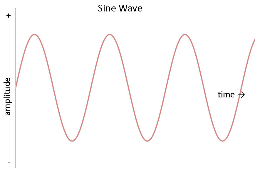
"Semiconductor dimmers switch on at an adjustable time (phase angle) after the start of each alternating current half-cycle, thereby altering the voltage waveform applied to lamps and so changing its RMS effective value. Because they switch instead of absorbing part of the voltage supplied, there is very little wasted power." So a really fast switch that chops the sine wave and limits the voltage to a device (incandescent lamp hopefully).
The rack Control Electronics Module (CEM) does the conversion of whatever data signal comes off the console (DMX, sACN) and instructs the dimmers as to when to switch and which dimmers should be doing what.
ThruPower modules have 2 built in mechanical relays (as well as the Solid State Switches for dimming) that can have the dimming load transferred to feed thru the relay on the module. This bye-pass of the dimmer portion of each half of the module can be either set via switches on the module, or (rack and console dependent) can be set via software called Concert, where you can configure your racks and assign a module to be a D20 dimmer, R20 relay module or TP20 ThruPower module, among others.
tjrobb
Well-Known Member
To add to SteveB (who is an expert on dimming), this is how we get forward- or reverse- phase dimming. Forward is where the dimming waits until partway through the wave then turns on, reverse waits to turn off. Because it's turning off, reverse tends to be gentler and less noisy. (Basically, the filaments hum because of the chopping, if I remember).
JonCarter
Well-Known Member
What we refer to as "120 volt" power is an AC voltage that varies from 0V to roughly +170V at a 60 Hz rate, the average voltage being 120V. [For the mathematically inclined, for a sine wave the RMS voltage is 0.70711 times the peak voltage, or the peak is 1.4142 times the average.] This results is "100% brightness" of a lamp designed for "120V" operation. The electronic dimmers take this "120V" input power and switch it at varying points in the power cycle. At reduced dimmer settings, only a part of the entire sine wave of the incoming power (the point varying with the dimmer setting) is at the dimmer's output. The average voltage of this output is a voltage lower than 120V, therefor a lower light output for the 120V lamp.
To add to SteveB (who is an expert on dimming), this is how we get forward- or reverse- phase dimming. Forward is where the dimming waits until partway through the wave then turns on, reverse waits to turn off. Because it's turning off, reverse tends to be gentler and less noisy. (Basically, the filaments hum because of the chopping, if I remember).
Perhaps you're thinking of that other famous Steve - last name of Terry !.
I think you're "Steve the infamous" and Steve Terry is merely famous.Perhaps you're thinking of that other famous Steve - last name of Terry !.

I think you're "Steve the infamous" and Steve Terry is merely famous.
Like
JChenault
Well-Known Member
It seems to me that some basics have been assumed in the earlier answers. To the OP - apologies if this is too basic to be useful. I will be talking about the SCR dimmer - but triacs are similar.
First of all - lets make sure we understand what AC power is. ( Probably all you will run into these days). The key to AC power stands for alternating current. IE the current on the hot leg moves from positive to negative over a period of time, In the US this is usually 60 times a second. England I believe is 50 times a second.
In the late 50's the electronic folks developed something called the silicon controlled rectifier. Now a n SCR is a type of diode that controls the flow of current so if you put a diode across the sine wave ( the output might look something like this. ( Extremely crappy resolution. Sorry)
If you look at a diode, it has two wires coming out of it, and the electricity can only go one way.
What an SCR ( Silicon controlled rectifier ) does is to provide a third wire. If you provide a trigger voltage to that third wire, the SCR will 'Turn Off' until the voltage on the line crosses to 0. IE if you have an SCR in the circuit and do not apply a trigger voltage, it will stop all of the electrons trying to go in one direction. If you provide a trigger voltage, it will pass electrons through the SCR until the voltage on the line goes to 0 and will switch off.
So the way it works is you have two SCR's ( one for positive voltage, one for negative ) that get a precisely timed trigger voltage that electrons to pass through the SCR for the remainder of that cycle.
In the original designs, the timing of the trigger circuit was all by analog means. Today the timing is via onboard computers.
Note that this entire system mandates alternating. This is the reason in took so long for SCR dimmers to hit broadway. Most of the houses used DC power for the lighting, and it was not until Chorus Line ( which moved from Joseph Papps Public Theatre where they did have AC current) that AC power appeared on Broadway ( along with the first computerized lighting console )
First of all - lets make sure we understand what AC power is. ( Probably all you will run into these days). The key to AC power stands for alternating current. IE the current on the hot leg moves from positive to negative over a period of time, In the US this is usually 60 times a second. England I believe is 50 times a second.
In the late 50's the electronic folks developed something called the silicon controlled rectifier. Now a n SCR is a type of diode that controls the flow of current so if you put a diode across the sine wave ( the output might look something like this. ( Extremely crappy resolution. Sorry)

If you look at a diode, it has two wires coming out of it, and the electricity can only go one way.
What an SCR ( Silicon controlled rectifier ) does is to provide a third wire. If you provide a trigger voltage to that third wire, the SCR will 'Turn Off' until the voltage on the line crosses to 0. IE if you have an SCR in the circuit and do not apply a trigger voltage, it will stop all of the electrons trying to go in one direction. If you provide a trigger voltage, it will pass electrons through the SCR until the voltage on the line goes to 0 and will switch off.
So the way it works is you have two SCR's ( one for positive voltage, one for negative ) that get a precisely timed trigger voltage that electrons to pass through the SCR for the remainder of that cycle.
In the original designs, the timing of the trigger circuit was all by analog means. Today the timing is via onboard computers.
Note that this entire system mandates alternating. This is the reason in took so long for SCR dimmers to hit broadway. Most of the houses used DC power for the lighting, and it was not until Chorus Line ( which moved from Joseph Papps Public Theatre where they did have AC current) that AC power appeared on Broadway ( along with the first computerized lighting console )
tjrobb
Well-Known Member
STEEEEVE!I think you're "Steve the infamous" and Steve Terry is merely famous.
Yep, got them switched. Whoops.
@tjrobb As long as their wives don't make the same error, no harm done. (fortunately both Steve's are big boys and this'll slide off their shoulders.)STEEEEVE!
Yep, got them switched. Whoops.
Toodleoo!
Ron Hebbard
JD
Well-Known Member
Most dimmer "modules" are just the work end of the dimmer and simply contain a SSR (Solid State Relay), Choke, and circuit breaker. The choke is there to filter out noise. All the "magic" happens in the SSR. The SSR is a high speed switch and contains a number of parts all potted in epoxy. These include an opto-isolator (which prevents big power from flowing into the control circuit), a firing circuit, and either a pair of SCRs or a Triac to handle the real power. The rest of the "dimmer" circuit is on a control card, often called "the brain." This part does all the fancy stuff like decoding the DMX and figuring out the timing of the incoming waveforms and when to tell various SSRs on various channels when to fire.
Relay modules are a simpler circuit. In this case, there is no high speed switching, just a command from the brain that tells the relay to close and the light or other load to go to full. As such, there is little need for a choke to filter things. Depending on the brand, you may have to tell the brain which type of module you are using.
Relay modules are a simpler circuit. In this case, there is no high speed switching, just a command from the brain that tells the relay to close and the light or other load to go to full. As such, there is little need for a choke to filter things. Depending on the brand, you may have to tell the brain which type of module you are using.
Chris Pflieger
Well-Known Member
With SCRs, you're limited to just forward phase. With IGBTs and MOSFETs you can do either forward or reverse phase dimming... But why not both?
I always thought it would be useful to clip off the leading and trailing edges symmetrically to reduce the dv/dt, hence reducing the lamp sing.
Does (or did) any manufacturer do that? Is there any existing patents on that? Would modern LEDs throw a fit if that waveform was presented to them?
I always thought it would be useful to clip off the leading and trailing edges symmetrically to reduce the dv/dt, hence reducing the lamp sing.
Does (or did) any manufacturer do that? Is there any existing patents on that? Would modern LEDs throw a fit if that waveform was presented to them?
JD
Well-Known Member
The problem I would see with leading and trailing chopping would be that the dismal power factor would become abysmal! One of the problems with switch-mode power supplies is they only draw current at the peak of the AC waveform, when the line voltage exceeds the standing voltage in the main capacitor. By having dimmers only draw at the center of the waveform, your PF would plummet. The ultimate dimmer would draw linear current throughout the waveform and put out a pure sine wave... Kind of like an autotransformer!! Currently the closest we have are pure sine wave IGBT dimmers, but although they put out a sine wave, their current draw looks more like a switch-mode power supply and therefore presents a low power factor.
Last edited:
So why did we get rid of them rather than design a way to make them behave like we wanted?
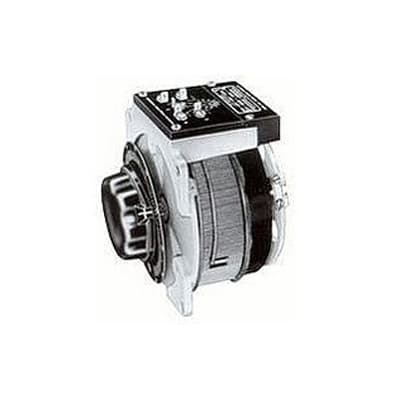
Autoformers? They are physically big, operate mechanically, and produce copious amounts of heat. Mechanical operation means slow response. A rack of dimmers would become a room of dimmers. Even the Ariel Davis sliding (linear) autoformer took a lot of space in any real quantity.
There were all sorts of dimming methods through the decades before the SCR/Triac came along. None of them were as affordable, efficient, compact, and controllable. The noise from a chopped sine wave is a small price to pay.
STEVETERRY
Well-Known Member
So why did we get rid of them rather than design a way to make them behave like we wanted?
Solid state sine wave dimmers enjoyed a brief run in our industry around 2003-2010. They went away for a few reasons:
1. High cost. Sine wave dimmers had 2X-3X cost penalty on SCR dimmers, even at unrealistically low price subsidies from manufacturers. And, while oversized SCR dimmers were almost free, increased power in sine wave dimmers did not have a linear effect on price. Yet, despite compelling evidence (see: http://www.etcconnect.com/workarea/DownloadAsset.aspx?id=10737494302) the industry was unwilling to "right-size" dimmers to loads, or back off the 20A per circuit standard in North America. The contributed to the lack of expected cost reduction in sine wave dimming.
2. Reduced Reliability. Sine wave dimmers are an order of magnitude more complex than SCR dimmers, with an associated reliability reduction.
3. Did not live up to "any load is OK" claims. Despite the assertions of multiple manufacturers that any type of load could be dimmed ("just like an autotransformer"), experience proved that this was not the case, which exacerbated (2) above.
4. Reduced density. Sine wave dimmers were typically half the density of SCR dimmers.
5. It turned out that almost nobody cared. The motivation for sine wave dimmers was quiet filaments. However, there were very few users willing to pay the price in dollars and reduced reliability. They started out on specs, but were generally value-engineered out when the high price was revealed. In addition, filaments were already getting much quieter due to the dominance of HPL compact filament lamps. I like to call sine wave dimmers "The party we gave where nobody came."
6. The rise of LED fixtures with built -in dimming. I think in 15 years we'll struggle to remember what a dimmer was, let alone a sine wave dimmer.
ST
Last edited:
BillConnerFASTC
Well-Known Member
Well, maybe not quite 15 but you can count on a few of us to rehash dimmer history from saltwater forward for a while yet.
JD
Well-Known Member
Yes, dimmers are fading into the history books! My prediction is that the next "big" driver for LED fixtures and dimmers will be something we don't pay much attention to right now- Power Factor. Currently, utilities bill us based on "real" power, not "apparent" power. HOWEVER, electric "smart" meters are capable of measuring both. As we rely more and more on switch-mode power supplies in almost everything, I suspect power companies may push to move to billing "apparent" power consumption as much of their infrastructure has to deal with the higher current levels presented by poor PF loads. In other words, your bill would be based on KVAh as compared to KWh. This is already happening in the commercial market where a business that presents a low overall PF load may be charged at a higher rate.
So, why does this matter? Although standards have been set for fixed indoor lighting, there are no current standards for the PF of "plug in" devices. As such, much of what is being manufactured has a lousy PF rating. In the lighting world, we plug in a LOT of stuff, enough to change a building's PF rating. Should a move be made by utilities to move to "apparent" power billing, manufacturers will be forced to bring better PF equipment to market, and we may find an entire generation of equipment becomes obsolete overnight!
So, why does this matter? Although standards have been set for fixed indoor lighting, there are no current standards for the PF of "plug in" devices. As such, much of what is being manufactured has a lousy PF rating. In the lighting world, we plug in a LOT of stuff, enough to change a building's PF rating. Should a move be made by utilities to move to "apparent" power billing, manufacturers will be forced to bring better PF equipment to market, and we may find an entire generation of equipment becomes obsolete overnight!
Chris Pflieger
Well-Known Member
I'll balance it with having other dimmers that chop out the middle of the waveform!The problem I would see with leading and trailing chopping would be that the dismal power factor would become abysmal!
Fine by me. If I never have to design another dimmer again, I won't regret it. Mostly because running tests with 9600 watt load banks in the summer sucks. Big time. And it used to be you could test with some resistors, a few lamps, and a Philips Mark X and call it good. Now I have to have a menagerie of LED lamps.
Most of our sales (arch. lighting control) are 0-10V, what phase cut dimmers we do sell are probably dimming track heads and other MR16/GU10 loads.
David Ashton
Well-Known Member
It's way more complex than P.F. in the old days a capacitive or inductive load would shift the P.F. and factories would have rooms of capacitors to correct it but with wave chopping and switch mode power supplies the wave forms are being distorted to hell and neutral currents can be more than per phase current, dimmers load up the beginning or end of the waveform and switch mode load up the middle, all in multiple constantly changing ways.
Similar threads
- Replies
- 5
- Views
- 415
- Replies
- 12
- Views
- 1K
- Replies
- 2
- Views
- 272
Users who are viewing this thread
Total: 1 (members: 0, guests: 1)