115 volt AC to 220 volt AC

byrnebox

Member
So this might be a stupid question. But I am going to ask it non the less. I have done some searching around and can not find an answer to this. Any help is appreciated. Thanks in advance.

Can you take 2 115 VAC circuits and turn them into 220 by just connecting the neutral and the grounds and using the 2 hot leads for each side of the 220?

If so you get the amperage of the 115 V circuits right? Here is what I am thinking about doing. Get 2 115 VAC circuits at 20A and make them 1 220VAC circuit at 20A. Let me know if that will work.

Thanks again.
 
If you're asking this question you should be calling an electrician.
Purely for educational purposes I will supply this diagram.
proxy.php
 
Last edited:
If the two 120V circuits are on the same phase, the potential difference between the hots is zero volts, so that's a no.

If the two 120V circuits are on different phases, the potential difference between the hots is 208 volts, so this might work. However, it is forbidden by the NEC. [Citation needed.]

Essentially, you'd be making this, with all genders reversed:
proxy.php

PowerFLEX Cable Assemblies: 3Phase 3Fer | Lex Products

I've seen some companies use these type of "cheater" cords to power 3Ø chain hoists, but they're illegal. The only approved method is to use a Rotary Phase Converter.

EDIT: See this device: Voltage Converter: 220 230 240 Volt Power from 110 115 120 Volt Outlets
 
This also depends where you are at. Large commercial buildings are likely to have 120/208Y 3ph power while very small buildings and homes will have 120/240 power.
 
I've heard a cable that does this called a "Suicide Cable".

So...
 
A suicide cable is the sort that has two male ends that are wired together. This would only be exciting if there was a hot/neutral fault somewhere. One hot netural fault and you've shorted a hot to a neutral, depending on the order you plug them in, it's 50/50 you make a suicide cable or pop the breaker, two hot neutral faults and you've shorted two hots, which is just not a fun time, /and/ you're powering your 220V device with two neutrals. Either way not so good.
 
This would only be exciting if there was a hot/neutral fault somewhere.

Sorry, wrong.
If you have a load connected phase to phase, let's say for the sake of this example it's a boring incandescent lamp. The average lamp has a few ohms of impedance when cold.

With the load connected, plug one plug of this "adapter" in. Now go and grab the active pin on the other connector. You WILL get a shock (assuming that the first circuit is energised). You'll be presented with basically the same situation as sticking your finger in the original socket...

It would be possible to make a device that takes 3 single phase inputs and renders a three phase output (given relevant sources) and was safe. You could do it with interlocks so that nothing energises until all inputs are connected and also disconnecting everything if one of the inputs is lost. I doubt it would pass code compliance, but it would be safe.

As to what the OP wanted, IF and only IF the supply is a split single phase will there be any chance of getting 230 out of the arrangement.

Involve transformers or isolated supplies and all this goes out the window, 2 115V sources can be made into a 230V source easily, safety issues would still be relevant...
 
Hah, you're right, if the load was connected then yes, you'd get a nice little shock. Suicide adapter it is!

Funny because just earlier today I was working on the exact same sort of thing: an outlet connected to a switch where the hot and neutral were reversed. The neutral metered 120V to ground, but the hot only read anything with a load connected - I should have made that connection.

With the load connected, plug one plug of this "adapter" in. Now go and grab the active pin on the other connector. You WILL get a shock (assuming that the first circuit is energised). You'll be presented with basically the same situation as sticking your finger in the original socket...
But hey, it would work, right? The lamp would light up? I think we have a solution here - now we just need a few sacrificial conductive actors.
 
... It would be possible to make a device that takes 3 single phase inputs and renders a three phase output (given relevant sources) and was safe. You could do it with interlocks so that nothing energises until all inputs are connected and also disconnecting everything if one of the inputs is lost. I doubt it would pass code compliance, but it would be safe. ...

From Voltage Converter: 220 230 240 Volt Power from 110 115 120 Volt Outlets, cited above:
  • Meets UL Standard 1012
  • Tested and Listed by Intertek, a laboratory approved by OSHA to test products for workplace safety.
  • Patented safety circuit checks and automatically locks out power circuits until connections and voltages are correct.
  • Interlock immediately and simultaneously electrically disconnects all input and output power lines if one of the 110/120 volt cords becomes disconnected or loses power.
 
hubbell actually makes a device that does this and has safety interlocks to keep the output from being energized if the inputs are not correct. Its made for marine use, i dont know offhand if its listed.
 
Here's the thing- Unless the breakers feeding the circuits are common trip (same handle for both circuits), you set the stage for a dangerous situation. For instance, if circuit "A" trips, circuit "B" would then be able to back-feed power into circuit "A" by way of the 240 volt device bridging the circuits. This may put someone at risk who is trying to repair circuit "A" as they would believe that it should be a dead circuit because the breaker is off. The whole concept is a big no-no.

Just a semantic correction on the title- On single phase, voltages would be 110 / 220 or 115 / 230 or 120 / 240 depending on what your local utility feels like giving you. On three phase it would be 120 / 208 (or any similar ratio) due to the phase lag.

the interlocked devices shown disconnect the load if one phase is lost.
 
Here's the thing- Unless the breakers feeding the circuits are common trip (same handle for both circuits), you set the stage for a dangerous situation. For instance, if circuit "A" trips, circuit "B" would then be able to back-feed power into circuit "A" by way of the 240 volt device bridging the circuits. This may put someone at risk who is trying to repair circuit "A" as they would believe that it should be a dead circuit because the breaker is off. The whole concept is a big no-no.

Not on something that is interlocked.
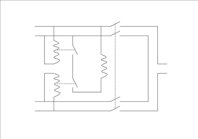
Basically how I'd set it up, and the commercial product will have a similar concept is a relay fed from each incoming supply. NO contacts of each supply's relay are looped together so that all supply's relay contacts are in series and that circuit would feed the coil of a contactor to connect the incomings to the outgoing and any commoning.

Just a semantic correction on the title- On single phase, voltages would be 110 / 220 or 115 / 230 or 120 / 240 depending on what your local utility feels like giving you. On three phase it would be 120 / 208 (or any similar ratio) due to the phase lag.

Perhaps we could stick to IEC standard voltages, 115/230 and 115/200...
 
I will defer to Steve Terry should he drop by, but I do not know of any code application that allows two independent 20 amp ~120 volt circuits, with no common trip, to be recombined to form a single ~208/240 circuit, especially post outlet.
 
Not on something that is interlocked.
Basically how I'd set it up, and the commercial product will have a similar concept is a relay fed from each incoming supply. NO contacts of each supply's relay are looped together so that all supply's relay contacts are in series and that circuit would feed the coil of a contactor to connect the incomings to the outgoing and any commoning.


Perhaps we could stick to IEC standard voltages, 115/230 and 115/200...

Your relay scheme still would not prevent an accidental backfeed of the supply circuits. Why? Because any control circuit has to draw current, unless it has an infinitely high input impedance. Basically, that is impossible. There is no way to do what you describe without creating a hazard and violating the NEC.
 
Your relay scheme still would not prevent an accidental backfeed of the supply circuits. Why? Because any control circuit has to draw current, unless it has an infinitely high input impedance. Basically, that is impossible. There is no way to do what you describe without creating a hazard and violating the NEC.

The NEC is moot, I said earlier that this won't make code. Oh and it's not applicable here...:twisted:

I've done a schematic so there's no confusion what I mean. I can't see how that can backfeed with a supply absent. While everything's live, sure and any RCD on those feeding circuits will trip.
 

Attachments

  • Interlock.jpg
    Interlock.jpg
    21 KB · Views: 1,572
Chris, from a quick glance it appears that the top-left relay is redundant. The top-right relay can't energise if there's no voltage on the top incoming line anyway.
 

Users who are viewing this thread

Back