
Yeah I would call Lehigh and describe your problem and ask them if they think it's a bad SSR and ask them for the part number and the name of your local Lehigh dealer... this of course assumes you figured out what model dimmer rack you have. Maybe you can even find a manual for your rack on their website or through them directly.
You are using an out of date browser. It may not display this or other websites correctly.
You should upgrade or use an alternative browser.
You should upgrade or use an alternative browser.
Channel Stuck?
- Thread starterSynchronize
- Start date
Actually, the answer is NO, except to put the module in a place where dimmer#1 on the module (which used to be 5, correct?) is in the least important place, a normally unused circuit perhaps? Then when the electrician comes, show him this thread, and explain what you've done, and suggest politely the replacement of the SSR. In the meantime, you could look at the SSR to see if there's a brand and model# on it so you can get an estimate of the price via the Internet. Like I said previously, these run $30-$50 generally. If replacing the SSR does not solve the problem, I'm afraid you'll have no choice but to contact Lehigh to see what they recommend.
Derek, yo say "no", then offer that advice? Ahem?

I'd say look at the module, don't touch, as we want to make sure the electrician sees it its as is condition, see if there is an obvious cause of failure: Completely charred? Disconnected/frayed/burned wire? Or, no visible sign of failure? Then it looks to be the SSR pack. Getting a price estimate and a model number could very much expedite the process.
When is he coming in again?
My feeling is leave the module alone (other than moving the module to a place in the rack that it isn't on a circuit that is in use). The less you go poking around in there the better. We are pretty sure it's a bad SSR. Call Lehigh and get the information about the part number and get your price quotes.
Synchronize
Active Member
There is no visable damage to any part of the module. The electrician should be coming in Thursday. If I understood correctly he does know lighting systems so it shouldn't be too hard for him to figure out the problem and find a solution.
There is no visable damage to any part of the module. The electrician should be coming in Thursday. If I understood correctly he does know lighting systems so it shouldn't be too hard for him to figure out the problem and find a solution.
As others mentioned, it is highly likely that the issue is a failed SSR pack. Do the recommend research, and politely suggest it to him.
Also be sure to check the pins (or make sure the electrican does) on the back of the module, they do sometimes get cooked and cause problems. I have also had trouble with the connector that connects into the control side of the ssr go bad and cause all sorts of weird problems excatly like you are describing. Also if the power pins are charred then both sides (the module and dimmer) connectors need to be replaced.
It may not be the SSR but the control circiutry that controls it.
There are the main control boards that do the DMX decoding but each module normally has a small of amount of cicuitry that actualy fires the TRIAC , SCR.
I don't know about this particular dimmer but I note on the Lehigh website I note another of their dimmers use TRIAC's not SCR's.
While trolling the web for info on this problem I was reminded of a problem I had on a single phase 4 channel kitset dimmer. This was a TRIAC setup. The channel had locked partially on but it wasn't the TRIAC but the optocoupler driving the gate. This was only a $1 part without testing the TRIAC would have been replaced without things getting any better.
Also Derek has mentioned buying replacement SSR's etc over the internet from non-original equipment manufacturer. Only do this if you know exactly what you are doing. Some parts may have only one charcter difference in their part number but the part is totally different or has different ratings. Also the person who sends you the part may not know the difference either.
As an exercise checkout the following link and try and workout which is the most robust TRIAC in the
BTB08-600 family.
http://www.onsemi.com/PowerSolutions/parametrics.do?id=826
There was an example recently of a parts store stocking what they thought was an insulated TRIAC but they had been supplied with the non-insulated version. If you don't know how dangerous that was then you shouldn't be messing around modules at a component level.
So unless you are skilled I would suggest always sending the module board to a licenced repair agent. This is also because they will have test jigs to run the module on safety with power flowing through it. This means they can take live voltage readings and not just guess what the problem is.
And I am not aiming this just at students, I know a lot of adults I would never let work on a dimmer pack.
There was an example recently of a parts store stocking what they thought was an insulated TRIAC but they had been supplied with the non-insulated version.
This happened to me recently. It was designed to switch a 250V cap on and off and there were two of them. Seeing two legs of 250 go to ground on a single piece of metal aint pretty. Made a bright purple light. Blew a hole through the piece of aluminum they were mounted on.
JD
Well-Known Member
As an exercise checkout the following link and try and workout which is the most robust TRIAC in the
BTB08-600 family.
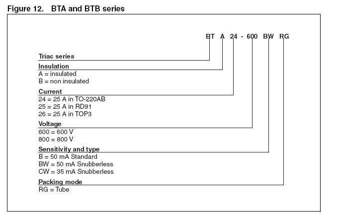
On triac numbers of the BT family:
BTA16 600B (for example)
BTB Non-insulated
BTA insulated
16 16 amp triac (not always the exact amperage, see below)
600 means that it has a breakdown voltage of 600 volts.
Also important is the case style. Three cases are used on the BT's. This can be tricky, here is an example of the 25 amp series:
BTA24 TO220A case (small tab like the four channel packs use)
BTA25 RD91 case (Round metal flange)
BTA26 TOP3 case (Larger flat plastic case)
I can think of no reason to use the non-insulated version, they are just trouble waiting to happen! The reason they are made is legacy. (They were around longer and some old equipment makes use of the flange. None in the lighting industry that I know of.)
EDIT: Oh, almost all dimmers use 50ma gate. (All that I know of) Snubber settings are not a factor unless you have a prehistoric dimmer that uses a pulse transformer as compared to an optocuppler. (Haven't seen any since the 70's)
Attachments
Last edited:
JD you went into more detail then I was expecting.
But this shows how carefully you have to read the datasheets.
The thing I was looking for on the particular part number I gave was the Di/Dt ratings are higher for one then another.
Also Ig is at 35mA for one and 50mA for the other. Put one that requires more Ig current then the control circuitry supplies and you get faulty operation.
Snubber circuits don't just apply to pulse transformer circuits. They are there to stop the current flow through the TRIAC's at the end of each AC half wave cycle so the current is cut off cleanly. Especially important when you are driving loads that may have some inductance eg transformer's etc. SCR's and TRIAC's turn on allowing current to flow through them when they receive a control pulse on the Gate pin.
But to turn them off the current going through them has to fall below a certain level else they won't cutoff. This normally happens at the end of each AC half cycle. An inductive load can generate back emf which causes enough current to flow back through the device to hold it on until the next proper firing pulse is received and it is turned on fully again. So that is why we use snubbers.
TRIAC's and SCR's have whole sections to themselves in tertiary electronic courses. So you can see why I say make sure you understand the parts before buying generic ones from a non-original supplier.
JD
Well-Known Member
Yea, an inductive load will have a flow pattern that looks more like a square wave. Although it must pass through zero, the time spent doing that is much smaller meaning an inductive turn off requires tighter V/us / A/us Di/Dt number to insure the device is off. Most dimmers also contain an external snubber in the form of an R/C network across the device as well to protect against both this effect and "flyback generation."
As far as Igt drive, I can't believe how universal that has become! My old (30 years) EDI packs use the same photo-coupler as the latest D4DL20 pack I serviced yesterday! All greatly exceed an Igt of 50ma. HOWEVER, you are correct in emphasizing the point that only a person with the proper training and experience should actually attempt service, or even parts id! In another recent thread I pointed out how even design engineers sometimes get circumvented by production "bean counters" to the detriment of the customer (16a triac on a 10 amp dimmer!) The aforementioned EDI packs used 130amp SCR bridges for a 2.4k 20 amp load, which is more in lines with what we learned as engineering students, to use a safety factor of 5 on solid state power devices.
EDIT: Which brings up "Frankendimmer" ! (My thoughts about resurrecting about 96k of old analog EDI I have, by ripping out everything up to the photocuppler, and replacing it digital!) (Please do not try that one at home!)
Last edited:
JD
Well-Known Member
Yea, never had to worry about those old systems taking a dump in the middle of a show. On the other hand, those old 100 pin snake connectors were never quite roadie proof!
<tangent>
Here's a tip that 25 years too late! I always found that those 50 pin phone connectors to be the most reliable! (and dirt cheap too)
</tangent>
<tangent>
Here's a tip that 25 years too late! I always found that those 50 pin phone connectors to be the most reliable! (and dirt cheap too)
</tangent>
Similar threads
- Replies
- 21
- Views
- 3K
Users who are viewing this thread
Total: 1 (members: 0, guests: 1)