michael728
Member
Hi I have been digging through the instruction manual and google searches but unable to find an answer to my question. Hoping someone here can help me.
I'm using an ETC Sensor cem+ touring rack, using 2.4k per channel and 48 channels.
So I've used this dimmer before a bunch of times but the hard patch has always been done by someone else and I've never learned how to do it.
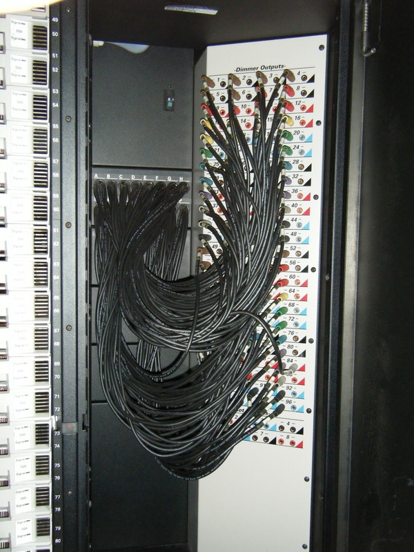
I have a basic understanding that the cable marked A1 normally goes into the area in the patch bay labeled 1, and the remaining receptacles can be utilized by other leads. A2 goes into 2 etcetera.
Now here's where I need help, the back of the rack has 16 socapex connectors, I'm only using 8 of them. I want to stagger the connectors so they're easier to access. Meaning the first socapex connector feeds channels 1-6. then the second one in line would be empty (because it's easier to connect and disconnect) and the third socapex connector would feed channels 7-12 and so on until I've used 8 of the 16 available socapex connectors.
How would I set this up in the patch bay? Do I plug the patch bay cable labeled "C1" into the receptacle labeled 7?
Thanks for the help.
-Edit
Now that i'm thinking about it.. not everyone's patch cables or socapex may be labeled like mine is. When I use these dimmers they come labeled. The Socapex connectors on the top row are labeled A through H the patch bay cables are color coded. The six red patch bay cables are labeled, A1 through A6. (I forget the rest of the colors off the top of my head)
I'm using an ETC Sensor cem+ touring rack, using 2.4k per channel and 48 channels.
So I've used this dimmer before a bunch of times but the hard patch has always been done by someone else and I've never learned how to do it.
I have a basic understanding that the cable marked A1 normally goes into the area in the patch bay labeled 1, and the remaining receptacles can be utilized by other leads. A2 goes into 2 etcetera.
Now here's where I need help, the back of the rack has 16 socapex connectors, I'm only using 8 of them. I want to stagger the connectors so they're easier to access. Meaning the first socapex connector feeds channels 1-6. then the second one in line would be empty (because it's easier to connect and disconnect) and the third socapex connector would feed channels 7-12 and so on until I've used 8 of the 16 available socapex connectors.
How would I set this up in the patch bay? Do I plug the patch bay cable labeled "C1" into the receptacle labeled 7?
Thanks for the help.
-Edit
Now that i'm thinking about it.. not everyone's patch cables or socapex may be labeled like mine is. When I use these dimmers they come labeled. The Socapex connectors on the top row are labeled A through H the patch bay cables are color coded. The six red patch bay cables are labeled, A1 through A6. (I forget the rest of the colors off the top of my head)
Last edited: