
Don Lomonaco CFCRC
Member
I'm posting this here because I was told that many ETC folks are around. I also chose Design Issues and Solutions because, in my research, I believe this lighting system was not designed with the 80% load rule in mind.
Hi all! We have an ETC Unison DRD 12-24-120 with 10 D20 modules and a CMeD control module. The entire Unison cabinet is wired to a dedicated 150 Amp breaker. We're using 19 circuits on those modules in the following way:
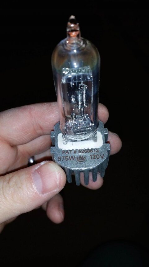
10 circuits each with 1 ETC Source Four 750 watt fixtures and a 575 watt lamp.
9 circuits each with 4 ETC Source Four PAR EA 750 watt fixtures with 575 watt lamps.
When we turn the all 19 circuits up all the way using our ETC SmartFade console we have a tendency to trip some of the dimmer module breakers that are wired to groups of 4 par cans. Doing the math it seems that four 575 watt lamps at 100% would require 2.3k watts on a 2.4k watt dimmer circuit. Am I correct in thinking that this plan is just too close to the maximum power available and that's why these circuits continue to trip?
Ok. With some further testing I have these results. I think we're close to getting to the bottom of this.
Circuit 1-4 lamps running will trip in 1:26.
Circuit 4-4 lamps running will trip in 0:33.
Circuit 3-4 lamps running will occasionally trip (time cannot be determined).
Circuit 9-4 lamps running will trip in 0:42.
Circuit 10-3 lamps running because 1 is burned out will not trip.
Circuit 2-3 lamps running because 1 is burned out will not trip.
Circuit 11-2 lamps running because 2 are burned out will not trip.
Circuit 12-3 lamps running because 1 is burned out will not trip.
Circuit 5-3 lamps running because 1 is burned out will not trip.
I've swapped out some modules from the circuits used to control the spots and the same banks of par cans trip regardless of the module.
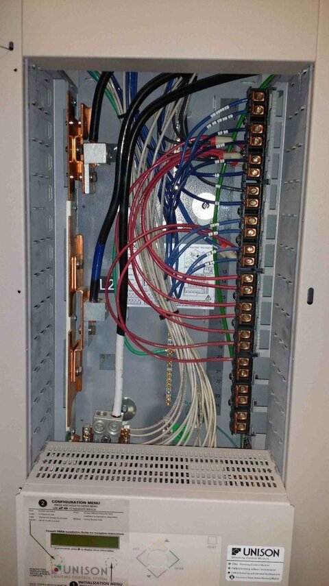
All lugs are secure. None were loose. After a general dust blasting all dimmers are back in place with the same results. I've attached a pic of the inside of the unit.
I'm checking wall outlets in the building while I arrange a lift in place and obtain a twofer to take measurements at the light source and to verify that each lamp is a 575 watt. Verdict so far: each outlet is reading 124.7 or 124.8 volts ac.
Ok. Maximum fader values for each troublesome circuit are:
Circuit 1-8
Circuit 4-7
Circuit 3-10 (continues to be intermittent)
Circuit 9-8
I scrolled through the menu on the command module and verified that each circuit is set to the correct module (the D20), it's set to incandescent, it's DMX channel corresponds to it's circuit number, and that dimmer doubling is off.
I've exchanged emails with ETC. Very helpful in their responses and even cc'd a local service company. The software can be reprogrammed. They also recommended lamping down.
Our current wiring is 12AWG/600volt/20AMP.
Final thoughts:
1. If we want to move to a 5k dimmer we would have to buy a 230volt DRD unit, upgrade the building wiring to 6AWG/600 volt/55AMP and purchase new dimmers.
2. Best solution may be to swap out 1 lamp out of the groups of 4 with a 375 watt and determine if this voltage reduction is enough to eliminate trips when the fader is raised to it's full value.
Hi all! We have an ETC Unison DRD 12-24-120 with 10 D20 modules and a CMeD control module. The entire Unison cabinet is wired to a dedicated 150 Amp breaker. We're using 19 circuits on those modules in the following way:
10 circuits each with 1 ETC Source Four 750 watt fixtures and a 575 watt lamp.
9 circuits each with 4 ETC Source Four PAR EA 750 watt fixtures with 575 watt lamps.
When we turn the all 19 circuits up all the way using our ETC SmartFade console we have a tendency to trip some of the dimmer module breakers that are wired to groups of 4 par cans. Doing the math it seems that four 575 watt lamps at 100% would require 2.3k watts on a 2.4k watt dimmer circuit. Am I correct in thinking that this plan is just too close to the maximum power available and that's why these circuits continue to trip?
Ok. With some further testing I have these results. I think we're close to getting to the bottom of this.
Circuit 1-4 lamps running will trip in 1:26.
Circuit 4-4 lamps running will trip in 0:33.
Circuit 3-4 lamps running will occasionally trip (time cannot be determined).
Circuit 9-4 lamps running will trip in 0:42.
Circuit 10-3 lamps running because 1 is burned out will not trip.
Circuit 2-3 lamps running because 1 is burned out will not trip.
Circuit 11-2 lamps running because 2 are burned out will not trip.
Circuit 12-3 lamps running because 1 is burned out will not trip.
Circuit 5-3 lamps running because 1 is burned out will not trip.
I've swapped out some modules from the circuits used to control the spots and the same banks of par cans trip regardless of the module.
All lugs are secure. None were loose. After a general dust blasting all dimmers are back in place with the same results. I've attached a pic of the inside of the unit.
I'm checking wall outlets in the building while I arrange a lift in place and obtain a twofer to take measurements at the light source and to verify that each lamp is a 575 watt. Verdict so far: each outlet is reading 124.7 or 124.8 volts ac.
Ok. Maximum fader values for each troublesome circuit are:
Circuit 1-8
Circuit 4-7
Circuit 3-10 (continues to be intermittent)
Circuit 9-8
I scrolled through the menu on the command module and verified that each circuit is set to the correct module (the D20), it's set to incandescent, it's DMX channel corresponds to it's circuit number, and that dimmer doubling is off.
I've exchanged emails with ETC. Very helpful in their responses and even cc'd a local service company. The software can be reprogrammed. They also recommended lamping down.
Our current wiring is 12AWG/600volt/20AMP.
Final thoughts:
1. If we want to move to a 5k dimmer we would have to buy a 230volt DRD unit, upgrade the building wiring to 6AWG/600 volt/55AMP and purchase new dimmers.
2. Best solution may be to swap out 1 lamp out of the groups of 4 with a 375 watt and determine if this voltage reduction is enough to eliminate trips when the fader is raised to it's full value.
")