Is my map wrong?

derekleffew

Resident Curmudgeon
Senior Team
Premium Member
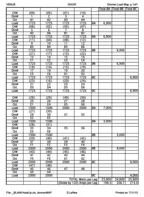
Here's the spreadsheet I've always used when circuiting an ETC Sensor 48x2.4 dimmer rack (PDF warning!):
9640t-my-map-wrong-dimmer_map.pdf

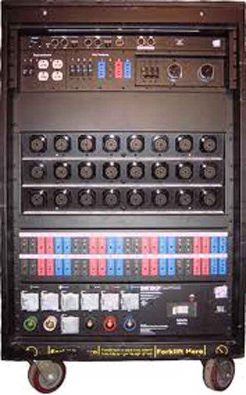
Which matches every rack touring rack I've encountered (or so I thought):
9641-my-map-wrong-89999230_xlarge.jpg


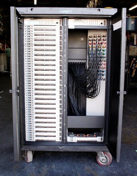
However, I've just found this picture on the interwebs:
9639-my-map-wrong-etc-48sensor.jpg


Anyone see the issue?
Have I been wrong all these years?
Hint: When did ETC start using 2P&G receptacle s of color? Is it standard or optional? I've never seen this in the wild.
.
 

Attachments

  • ETC-48Sensor.jpg
    ETC-48Sensor.jpg
    55.2 KB · Views: 1,099
  • dimmer_map.pdf
    57.3 KB · Views: 641
  • 89999230_xlarge.jpg
    89999230_xlarge.jpg
    212.5 KB · Views: 1,329
Last edited:
Since the "Go Advanced" doesn't work, I don't know how to fix that.:(

Here's a JPG of the same file:
9642-my-map-wrong-dimmer_map.jpg


.
 

Attachments

  • dimmer_map.jpg
    dimmer_map.jpg
    99.8 KB · Views: 873
Last edited:
Good Morning

The SP48 (48 X 2.4K) Has 3 buss bars (A, B, C)
It can be set for either balanced or straight.
In straight, dimmers 1 - 16 are phase A; Dimmers 17 – 32 are phase B And 33 – 48 are phase C
Straight down from slot 1, 2, 3, ……….
In balanced dim 1 & 2 are on Phase A, dim 3 & 4 are on Phase B, dim 5 & 6 are on phase C
Starting from slot 1 then skipping slots to slot 9 and slot 17 and back to slot 2 and so on
You can set straight / balanced in the SETUP menu
I can’t recall seeing the 3 color stage pin outputs but that would indicate a balanced rack
 
Last edited:
The map is not wrong. This rack, likely built for Show Lighting in CT, has a special config in the control module, stage pin connectors that we are no longer able to get, and some unusual wiring. Note that we do make touring racks standard and to people's specifications, so there are always rare caveats to the norms.

Some racks are 120/230V switchable, some have built transfer switches for alternate feeds, some are GFCI and some are RCD. Power output options are numberous.

The standard touring rack build is a phase on each of four modules. Now, most racks have D20 dimmers, which means eight dimmers on each phase, as the spreadsheet indicates. If using D50 or D100 modules, the number of dimmers per rotating phase changes. Even the rack in the pic has eight dimmers per phase, BUT the config and build calls out a phase balanced SR24 rack [installation rack] as the model. Why, I guess so as to get even more balancing than the 8 rotating dimmer count. Odd, but if you are running mostly smaller shows, this could come in handy.

Hope this helps. Please let me know if more info would be helpful. Perhaps I will post some pics soon.

David
 

Users who are viewing this thread

Back