LED Cue-light

Charc

Well-Known Member
So I could probably just figure this out tomorrow, but I thought this would be an interesting topic for the booth, and has some educational merit.

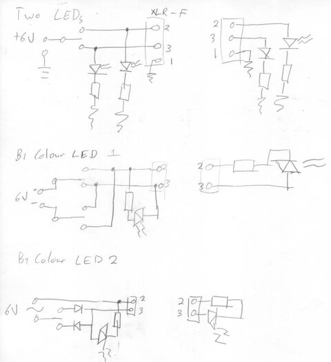
So today I was running XLR (20 minutes before the house opened!) with the ME for a newly home-brewed cue-light system. It was pretty interesting. A little DC power supply into a hobby box, with unknown electronics/wiring inside, two toggle switches and two XLR outs. The XLR was run from the hobby box to the cue-light location, and a small adapter was attached to the end of the run, also home-brew. He took a bare connector, and wired it up with the LED sticking out the hole where the cable would be... :grin:

Looked like a pretty nice little setup, and cheap/easy considering most theaters should have the parts on-hand.

How would you go about setting up this system? What would you do differently than described? How would you wire in the LEDs, any resistors, or anything else relating to the project?
 
Yea, and ProCue costs how much? We all know how Charc's school loves to spend.


Side note: TMB just gets to make all the fun widgets don't they?
 
...We all know how Charc's school loves to spend. ...
Stay with the program, Greenia. This is for Charc's internship at the professional theatre, and we all know that LORT theatres have virtually unlimited budgets.:rolleyes:

...Side note: TMB just gets to make all the fun widgets don't they?
Yes, whatever did we do before TMB and City Theatrical? I'll tell you--we made things ourselves, with varying levels of success and, in the long run, often more costly.
 
Last edited:
I guess I'm slipping, Derek. I guess I'll have to start both reading the board constantly AND start taking notes on everyone's life.

But what about the feeling of accomplishment that comes with making your own gear, or, I mean, the smashing your head into a wall when it fails?
 
I guess I'm slipping, Derek. I guess I'll have to start both reading the board constantly AND start taking notes on everyone's life.
But what about the feeling of accomplishment that comes with making your own gear, or, I mean, the smashing your head into a wall when it fails?

Or dealing with the SM who is smashing your head into the wall when it fails, thats usually how it goes.
 
OK I'll try and answer Charcoal's question before we forget it.

What you saw is fairly simple to build. It's a project you could easily handle.

First here is a quick link about wiring LED's.

http://white-leds.co.uk/led-wiring-guide.htm

Just remember different LED's have a different forward voltage. You normally find it listed in the suppliers catalouge.

You forgot to mention whether the LED was just one colour and how they used the cuing system. Ie Did they only turn the LED on just before the cue then off at cue time? If it was this is the simplest thing of all to make. You have your battery supply so you wire battery negative to one pin of the XLR in your control box. The battery positve is then wired to one side of a switch. From the other side of the switch you could use the resistor you need to connect the switch to another pin on the XLR . Then in the XLR plug for the other end you just wire the LED across the same two pins. That's all there is to it. To improve the LED end you put expoxy resin to fill the XLR cap to hold the LED in.

For a two location system like your LD's one just duplicate the above you can use the same battery supply. Note for battery you can also use a DC adaptor. I would use at least a 9V source.

For working out the value of the current limiting resistor I would set the current value higher then you need by 10 or 15 Milli Amps this will allow for the resistance of the cable.

Charcoal would you like to hear about a slightly more complicated unit that uses a two colour LED?
 
I made one about 30 years ago when leds were new technology, in the control box is a 3 volt transformer connecting to 2 switches, one switch connects to the anode of a green led and the other to the cathode of a red led.
then join the green cathode and red anode together to one wire and the other side of the transformer to the other wire on the 3v transformer.
At the other end of your 2 core cable a box with a red diode cathode and the green diode anode joined together to the "live" 3v wire and the other ends to the common wire
Basically the two green leds are in series on the positive half of the waveform and the two reds on the negative.
Very safe and very cheap.
 
Your diagram doesn't quite work but I think you have the idea but I'll go over it again to make sure.

We'll pick pin 1 to carry the common battery gnd (-)

The battery positive is connected through a suitable resitor to a two postion switch with centre off. Connect the battery to the common input of the switch.

Ie the one that if you put one leg of continuity meter on this switch contact leg and the other leg of the meter on either of the other switch contacts when you move the switch to the on positions you get a circuit made without having to move the lead off the common. Most of the time this is the centre connection.

Now you have detrmined the switch connections wire one side of the switch to pin 2 and the other to pin 3 of the XLR.

At the other end join the cathodes of both LED's together and wire to pin 1. Wire pin 3 to the anode of the RED led and pin 2 to the anode of the GREEN led.

To work it move the switch from the centre off position to one side then another making sure the Led's light in turn.

Try diagramming that but use three wires on your diagram.
 
Yes that's better you have got the idea but don't forget the current limiting resistor in the control box. It can either go in the - gnd or + leg it doesn't matter which..

Edit: Yes a couple of Led's in the control box that are in series with the ones at the far end is a good idea. This gives a fault check to the other end because if there is a wiring fault your LED wouldn't light being in series. 6V is the minium I would use.
 
Last edited:
Can you elaborate on the current limiting resistor?
Also, I want to confirm that I can wire 4 of these systems in parallel onto one 6V DC Power Supply.

Go back to the link I posted on how to wire up Led's earlier in this topic.
Remember Led's are current devices in that the more current they get the brighter they glow.

If you don't use a current limiting resitor it's a bit like getting into a car and holding the accelerator flat down while steering down a straight line. The car will go faster and faster and eventually you'll run out of road and smash your self to pieces. Think of the Led as that car driver just because he can draw more and more current don't mean it's good for him.

So a quick refresher to work out the current limiting resistor .
You have the supply voltage eg your 6V battery.
All led's have forward voltage drop which is like how much voltage the use up. A small Led' may have 1v ( rough figures for ease)
So take this voltage away from the supply voltage.
Now from the Led datasheet as well as the forward Voltage Vf you find the maximum current rating the Led can handle Imax.
Choose the current you need for small led's typicaly 20 milliamps is ok.
A bit of maths . ( V is in volts, I is in Amps, R is in ohms)
V = I x R rearrange to find out R our resistor value .
R = V / I so in our example
R = ( 6 -1 ) / 0.02 = 5 / 0.02 = 250

So our current limiting resistor would need to be 250 ohms and for simplicity use 1/2 -> 1watt resistors

For your thing of having 4 of these circuits from one supply that shouldn't be a problem at this low level of current. If using batteries use C or D cells as opposed to AA cells. If you use a DC adaptor rate it at say 200 milliamps current supply and you should be fine.

Hope this helps.
 
Electronics parts vendors:
Mouser
Jameco
Digi-Key

All good vendors with large selections.

MPJA has some odd components.
 
Last edited:
Now I'm going to be a pain here and pull up some of the terminology being used earlier... Someone was advocating wiring LEDs into the control box. Good idea. Wiring them in series as suggested, bad idea. To assist, find attached a quick circuit diagram as well as a couple of options for doing it with bicolour LEDs. Pin nos can be changed as you like... All bicolour options can just as easily be implemented with 2 normal LEDs back to back...

R value. You will be in a dark theatre, so brightness doesn't need to be great and if one uses lower brightness, you'll get better battery life but more importantly, less light leakage... So for 6V supply and 10mA current (Yes I know I should factor in forward voltage, but I'm not because the brightness don't matter and the "6V" coming out of an unregulated plugpack is likely to be even as high as 9v under minimal load), you go R= V/I = 6/0.01 = 600R.

With my designs above, you can add as many signal repeaters as are needed up to the rating of your transformer. Actually, the R could be commoned in circuit if you felt like it since the switching arrangement prevents the two from ever being concurrently on. At 10mA per signal, you'll probably run out of locations before you run out of juice...
 

Attachments

  • Cue LX.jpg
    Cue LX.jpg
    36.9 KB · Views: 895
Wiring them in series as suggested, bad idea.

Chris now you made the statement please explain it?

In my post I mentioned doing it in serial as a failsafe indicator. If the Led's on the control box fail then you know the Led's at the other end won't be lit either. I am talking about only having the same colour Led's in series on the same leg ie red - control -> red stage end

Chris with your way of wiring the control the Led's will light even if there is no cable plugged in for the other end.

Charcoal wants four channels so these are made as four separate circuits. I agree you can use one resistor per seperate control channel but I would have one resistor for each control channel not just one in the controlbox.

I had also thought of using Bi-Led's but decided to stick with the basics so once Charcoal can get a single Led working then he can get Bi-Leds working. If you have some old faulty XLR cable that only has two god conductors you could use a Bi-Led circuit with this instead of throwing it out.

Charcoal I also just thought of another use for this box of yours.
You can use it as a very simple good/bad XLR cable detector.

All you do is plug in the suspect XLR cable to the box add your Led plug on the end.
To test just switch the Leds on and off as normal. So when you have the red Led lit on control if the cable is good the red Led should be lit.. If the red Led doesn't light then either there is a fault on the conductor wired to the Led or the common ground is faulty. But if instead the green Led lights when the red one should there are wires swapped.
Just a note if you have wired the Led's in series like I suggested the if there is a broken connection then the control Led won't light either. But you know the switch position for each LED anyway. Wriggling the Led while it is connected may help to show loose connections.
 
Bi-Leds are one that actually have two colours in the same package, usually red and green.
Typically they have only two leads like a normal Led.
How they work is an Led is diode they only operate with the voltage supply hooked around one way.
So they just wire the two leds in opposite directions to the two legs.
Then by changing the polarity of the voltage you change which Led lights.
Eg to keep it simple we'll name the led legs 1 and 2.
Say the Red led is wired so it's Anode (+) is wired to pin 1 and it's cathode (-) to pin 2
Say the Green led is wired so it's cathode (-) is wired to pin 1 and it's Anode (+) to pin 2

So to turn on the red led connect the + battery to pin 1 and battery - to pin2, the green led stays off
So to turn on the green led connect the + battery to pin 2 and battery - to pin 1, the red led stays off

Just remember you still need a current limiting resistor in one leg of the circuit it doesn't matter which one.
 
Leds in series- good idea, its failsafe
Battery drive-terrible idea, the battery will die at some crucial point.
Bi-colour leds- terrible idea, you can only cue people who are not colour blind
The design I described earlier in this thread has run for 30 years without a fail and costs very little.
But why use 4 leds, 2 switches and a transformer when you can do the job just as well with twice as many components?
 
Chris now you made the statement please explain it?

In my post I mentioned doing it in serial as a failsafe indicator. If the Led's on the control box fail then you know the Led's at the other end won't be lit either. I am talking about only having the same colour Led's in series on the same leg ie red - control -> red stage end

Chris with your way of wiring the control the Led's will light even if there is no cable plugged in for the other end.

Charcoal wants four channels so these are made as four separate circuits. I agree you can use one resistor per seperate control channel but I would have one resistor for each control channel not just one in the controlbox.

I had also thought of using Bi-Led's but decided to stick with the basics so once Charcoal can get a single Led working then he can get Bi-Leds working. If you have some old faulty XLR cable that only has two god conductors you could use a Bi-Led circuit with this instead of throwing it out.

Charcoal I also just thought of another use for this box of yours.
You can use it as a very simple good/bad XLR cable detector.

All you do is plug in the suspect XLR cable to the box add your Led plug on the end.
To test just switch the Leds on and off as normal. So when you have the red Led lit on control if the cable is good the red Led should be lit.. If the red Led doesn't light then either there is a fault on the conductor wired to the Led or the common ground is faulty. But if instead the green Led lights when the red one should there are wires swapped.
Just a note if you have wired the Led's in series like I suggested the if there is a broken connection then the control Led won't light either. But you know the switch position for each LED anyway. Wriggling the Led while it is connected may help to show loose connections.

Leds in series- good idea, its failsafe
Battery drive-terrible idea, the battery will die at some crucial point.
Bi-colour leds- terrible idea, you can only cue people who are not colour blind
The design I described earlier in this thread has run for 30 years without a fail and costs very little.
But why use 4 leds, 2 switches and a transformer when you can do the job just as well with twice as many components?

Now it would seem I had misinterpreted Charc's thoughts on multiple units and that materially affects things. It was the thought of multiple units paralleled to display the same thing that induced the series bad comment. Because if each LED is pulling say 10mA and you have two or three remote units, then you'll be pulling 20 or 30mA through your control box LED and it'll be rather bright, probably a different colour, until it dies mid show from continual overload... 'Twould also need to change the resistor value.

My comment about using a common resistor was only in the case of tieing the Anodes of the LEDs together in Circuit 1 and a single resistor to ground instead of the two shown, but the isolation if something goes wrong wouldn't necessarily be a bad thing...

As I noted, it would the same using two separate LEDs wired as though they were a bicolour, though i they have radically different Vf values, you should use seperate resistors of appropriate values; you may need to do that anyway if you have mismatched brightnesses and this causes an issue... This use of two rather than a single would get around the colour blindness issue mentioned by David.

David, have you tried getting a 3V transformer of late? Besides, you really should still be putting in a current limiting resistor anyway...
 
Any cheap multitap transformer will have 3 volts between some windings,I didn't bother with series resistors but it still works, it will probably corrode to death before it fails, but if you need to run off a higher voltage then a resistor in each line would be needed.I actually cannibalized an old intercom unit for the master station and used all the old switches, I think the total cost for a 6 way system was $15.
 

Users who are viewing this thread

Back