
You are using an out of date browser. It may not display this or other websites correctly.
You should upgrade or use an alternative browser.
You should upgrade or use an alternative browser.
Martin Atomic 3000
- Thread starterSean
- Start date
Hi Irwin,
Thanks for helping out! I just used an ohm meter on D114 and its reading 1.2M ohms. When I switch my fluke to diode mode, I do get a beep, then get another beep when polarity is reversed.
I also looked for some BYD77 diodes and I can't seem to find any available anywhere.
I'll see what I can do about getting a scope to borrow, I don't have a ton of experience using a scope though. But this is a perfect chance for some experience on using a scope.
If C135 was bad, could that cause my symptoms? I removed the board from the panel to inspect the board closer. I noticed C135 might be slightly bulging. I measured with the multimeter but it measured open, I measured the other two that are the same caps near the mains and they also measured open. Not sure what to make of that.
Also is it correct that the secondary on the transformer measures a dead short?
JD,
I powered it on with the external power supply and plugged the main in and still got 5v on the 5v line.
Thanks for all the help guys!
Irwin
Member
You definitely should not be getting continuous beeping from your Fluke on both directions of the diode. That usually indicates a shorted diode. The transformer secondary should measure just over 1 ohm, not quite a dead short but close. I'm not sure what to make of C135 bulging.
The BYD77 is obsolete. If you need to replace it, you can substitute a BYG22D instead.
The BYD77 is obsolete. If you need to replace it, you can substitute a BYG22D instead.
Hi Irwin,
Sorry, I wasn't clear in my previous post, the beep wasn't continuous. It beeped on and off, then when I reversed polarity, it beeped on and off again.
I measured the secondary again and i'm getting a dead short. .2 ohm. Maybe the transformer is toast? It appears to be a Kaschke 4502000, but I can't seem to find any datasheets on it to find a replacement. Only info I found is it's a 3-10w transformer from a martin descriptions of the transformer.
Irwin
Member
Oops, my bad on the secondary measurement. My Fluke needs calibrating. I'm getting about 0.8 ohms when I touch my leads directly together, so that does indeed indicate about 0.2 ohms for the secondary.
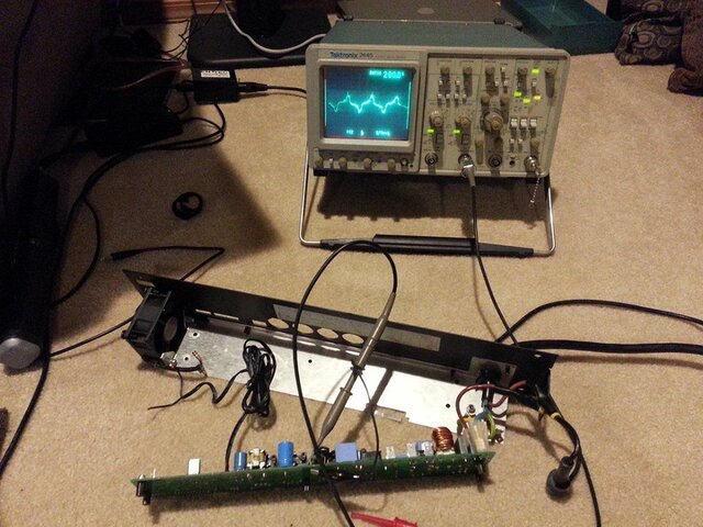
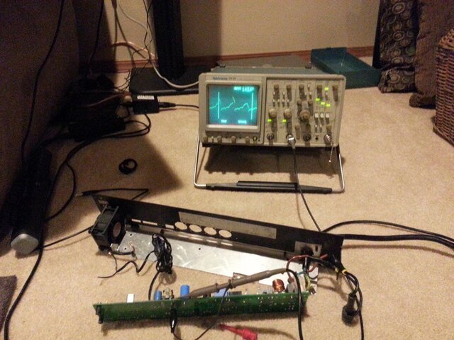
Try to get a scope across the secondary while the unit is plugged in. You should see an AC waveform of several volts at 130KHz. Then probe the other side of D114, and if there is a similar AC waveform, or almost nothing, then the diode is bad.
Try to get a scope across the secondary while the unit is plugged in. You should see an AC waveform of several volts at 130KHz. Then probe the other side of D114, and if there is a similar AC waveform, or almost nothing, then the diode is bad.
I can't seem to get any waveform out of the secondary or after the diode. I was able to get some kind of waveform from the primary and before the rectifier with the AC setting. I attached a couple pics of what I got. Of course it probably doesn't matter since the problem probably starts at the secondary.
Attachments
JD
Well-Known Member
Those spikes kind of look like a switch-mode power supply trying to start but kicking right into over-voltage or over-current protect. (Possibly a soft clicking or buzzing sound can be heard.) Some notes:
1) having that low a meter reading on the secondary of the transformer is probably ok, as the meter measures using DC so the resistance collapses.
2) Since it fires up with external DC, we know it is not a short on the 12 volt buss.
3) False over-voltage trip could be caused by one of the two zener diodes being bad (D117, D123)
4) You noted C135 was bulging. On my Schm C135 is not an electrolytic cap (the type that usually fail that way.) If the cap you are looking at is an electrolytic (can type) cap and it is bulging, replace it. Often, a bulging cap will go open circuit, which is just as bad as shorted.
Irwin
Member
Yep, if you're seeing input at the primary and nothing at the secondary, either the transformer is bad, or the secondary is being shorted by something externally.
I have a hunch which would be simple to test: if the diode D114 was indeed shorted, the capacitor C128 would have a very low impedance at 130KHz, effectively loading down the secondary output. Try lifting D114 from the circuit and see if you get anything at the secondary.
I have a hunch which would be simple to test: if the diode D114 was indeed shorted, the capacitor C128 would have a very low impedance at 130KHz, effectively loading down the secondary output. Try lifting D114 from the circuit and see if you get anything at the secondary.
Thanks for all the help guys, I'm learning a lot from this process.
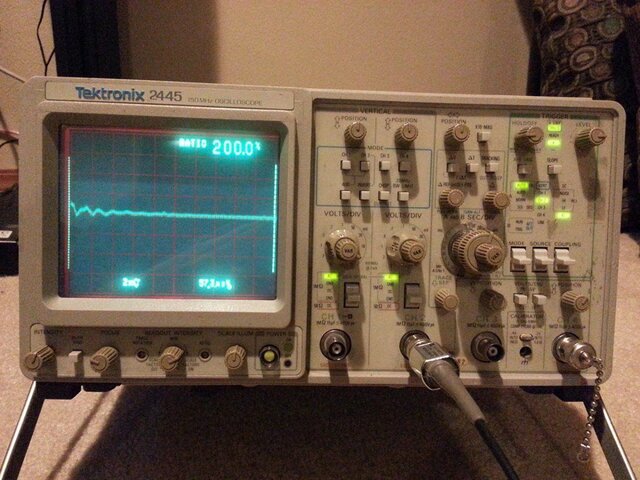
I lifted D114, I'm getting absolutely no dc voltage coming out of the secondary. I'm seeing 110v DC going into the primary.
I attached a pic of the scope reading on the secondary with D114 lifted.
JD,
C135 is a R41 MKT X1/Y2 safety cap. It's not round like an electrolytic cap. The dielectric material is Polypropylene (PP), Metallized according to the datasheet (http://www.kemet.com/Lists/ProductCatalog/Attachments/497/KEM_F3100_R41_Y2_300.pdf).
Thanks!
Attachments
JD
Well-Known Member
Looks like a pulse followed by a short ring. Something's telling the switcher to not bother try! Could be the transformer, but my gut tells me it's a simpler problem. What voltage are you getting across the transistor side of the opto-isolator? (pins 4-5) If that junction were bad, you would get close to 0 and the switcher would think the output of the transformer was in over-voltage.
Without the switcher running, the main supply cap C131 should be charging up pretty close to peak line voltage (about 180 volts at 120 volts in.) If it is a LOT less, than that cap might be open.
Without the switcher running, the main supply cap C131 should be charging up pretty close to peak line voltage (about 180 volts at 120 volts in.) If it is a LOT less, than that cap might be open.
Irwin
Member
In case you can't fix it...
http://www.ebay.com/itm/181584272804
http://www.ebay.com/itm/181584272804
Thanks for the heads up on the ebay board. I'll keep an eye on it.
JD,
With D114 lifted, I'm getting 280vdc on pin 4 and 5 of the opto isolator(IC111). I probed the Positive pin on the rectifier and pins 4 and 5 on the opto. If I continue to probe it, the voltage slowly starts dropping. I measured across C131 and am getting 280vdc.
Thanks!
JD,
With D114 lifted, I'm getting 280vdc on pin 4 and 5 of the opto isolator(IC111). I probed the Positive pin on the rectifier and pins 4 and 5 on the opto. If I continue to probe it, the voltage slowly starts dropping. I measured across C131 and am getting 280vdc.
Thanks!
Irwin
Member
Hmm, something is way off. If you are plugged into 120V mains, you should be getting about 160-170vdc across C131. I would expect to see 280vdc across C131 only if you were plugged into 208V mains. Also, the voltage you're seeing between pins 4 and 5 of the opto isolator is way too high.
With D114 still lifted, you should see the following voltages on the TNY255:
Between pins 8 and 1: 5.8vdc
Between pins 8 and 4: 1.5vdc
With D114 still lifted, you should see the following voltages on the TNY255:
Between pins 8 and 1: 5.8vdc
Between pins 8 and 4: 1.5vdc
It's weird. When the main is first plugged in (120vac), Measuring across C131, I get 170vdc, and it continues to rise and it finally settles around 280vdc after 20secs or so.
With D114 still lifted
Measuring across pin 1 and 8 on the TNY255, I get .014vdc
Measuring across pin 1 and 5 on the TNY255, I get .215vdc
With D114 still lifted
Measuring across pin 1 and 8 on the TNY255, I get .014vdc
Measuring across pin 1 and 5 on the TNY255, I get .215vdc
JD
Well-Known Member
Measurements to pin 1 are not going to be too useful. Sorry this pic is in Russian and it's a 220v circuit, but it does help simplify the discussion. Look at the voltage between pin 2 (or 8,7,6,and 3) and pin 5. If that is also near the full cap voltage, then the TN255 is locked off probably in a protect mode. If it is very low, then the primary of the transformer may be open. Then look at pin 2 to pin 4. if that voltage is less than a volt then the opto might be popped. Little baffled by the supply cap drift as no reason comes to mind as to the voltage climbing so high as the circuit is not a pumper.


I'm using a simple fluke multimeter to check the voltages, the model escapes me at the moment. There's no fancy features on the meter, just AC, DC, Diode check, and amp reading. Before I lifted D114, the voltages were around 160vdc.
I'll check it out over the weekend when I get some time and report my findings for your JD.
I'll check it out over the weekend when I get some time and report my findings for your JD.
JD
Well-Known Member
I'm using a simple fluke multimeter to check the voltages, the model escapes me at the moment. There's no fancy features on the meter, just AC, DC, Diode check, and amp reading. Before I lifted D114, the voltages were around 160vdc.
I'll check it out over the weekend when I get some time and report my findings for your JD.
Tangent>>
Ah! By lifting D114 you created a pump! The flyback on the primary being switched by the TNY pushed C131 higher! In any case, it sounds like the transformer and the TNY are working fine. I would look next at the voltage between pin 2 and 4 to see if the opto is shutting it down. Whatever you do, don't open the pin 4 / opto loop as that would cause a runaway reaction in the switcher.
JD,
I did some more tests as you suggested. I'm noticing weird things now, I put D114 back in circuit, and the C131 starts at 315vdc and settles around 270vdc. I know when we first started troubleshooting, I was getting around 160vdc at C131.
Measuring pin 2 and 4 on the tny255, I saw it slowly rise from .5vdc to 1.7vdc then drop back down to .3vdc. It doesn't seem to settle, it will slowly rise and appears to slowly drop.
Measuring pin 2 and 5 on the tny255, I'm getting .44vdc
I do hear a really faint buzzing too coming from around the transformer area.
Not sure what to make of the weird voltages we're seeing from the rectifier, especially after putting D114 back in circuit. Using the diode test function on the multimeter is showing D114 is good.
Thanks again for all your help.
Similar threads
- Replies
- 0
- Views
- 1K
- Replies
- 4
- Views
- 3K
Users who are viewing this thread
Total: 1 (members: 0, guests: 1)