old Electro Controls system questions

mvp1114

Member
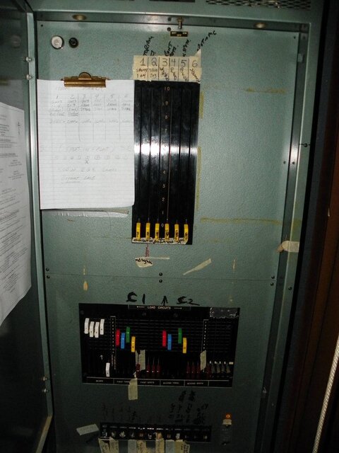
OK, I’ve got several questions on the same subject so I’m going to split them up into a couple of threads. Background: I got tapped to do sound again for a local Serbian Orthodox school's show (yes, they still speak Serbo-Croat-whatever there - last year’s show was "Scroogevitch"; try following a cue sheet & script with that stuff thrown in!) and got roped in to look at the lighting system. (see Photo 1)

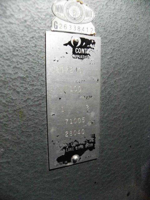
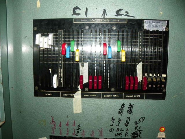
It's an old Electro Controls wall-mount console with the quick-connect slider patch bay, 6 dimmers, 25 load circuits, but the model badges are pretty scratched off – I THINK it’s model 71005, S/N 28040, but you can see how scratched off it is, and the silver embossed EC decal on the slider patch panel is pretty illegible too (see photos #2 & 3). (Luckily my current high school used to have a big old Ariel-Davis system with the same setup, but a lot bigger, that I got to work on a lot before we were able to replace it).

After I disconnected some truly decrepit fixtures and figured out some of the circuits, I actually got it going relatively well but in a limited way – nine “front spots” (Electro Controls 3366F’s, 500W EGE’s) and the six borders (Electro Controls 36615’s – four colors/four circuits per fixture/16 lamps per border, 100W lamps).

Question #1 – what model is the console? I need to find a schematic (and wouldn’t mind a manual). I’d like to be able to show the folks there everything the system can do for them, AND I’m working on getting them to get a good electrician in there to at least clean everything up . . . dream on, right? Can you all tell anything from the defaced badges?

Question #2 – There was a penciled-in scribble sheet on the board that said the dimmers were 2000W, but the border lights alone would be 2400W per color circuit if they were all relamped (that’s in process). Since I have to assume that everything was installed together by professionals (based upon the ages of the lamps, in the early 1970’s so I assume the board is same age, since it’s not Ariel-Davis branded), what do I assume? If I go by the 2000W penciled in limit, I need to leave 24 sockets among the six borders empty (4 empties per color). Pro installers wouldn’t have done that, would they?

I’ll ask the next questions in another thread. Thanks!

Mike
 

Attachments

  • Photo-1.jpg
    Photo-1.jpg
    101 KB · Views: 631
  • Photo-2.jpg
    Photo-2.jpg
    73.2 KB · Views: 510
  • Photo-3.jpg
    Photo-3.jpg
    121.5 KB · Views: 740
Old Electro-Controls system questions #2

Second post – old Electro Controls system – see above thread for photos & background

Question #3 – There are a total of six dimmers. Even if I assume that they are 2400W dimmers, I can’t figure out how everything could have run at once. The “spots” labeled on channels 10-13 and 18-21, as far as I can tell because they are burnt out, are eight pairs of old ElectroControls 6” fresnels with the old fist-sized bayonet base lamp at 500W each (I’ve unplugged the fixtures as I really don’t want a fire on my watch).

How many blinkin’ watts are each of those dimmers rated for? My totals come out to (9)x500W=4500W for the front spots, (16)x100Wx(4)=9600W for the borders, (16)x500W=8000W for the fresnels = 22,100W; divided among six dimmers would have to be 3683.33W per dimmer – so are 4KW dimmers possible for this system (never mind smart, just possible)? That doesn’t even figure in the four “extra” load circuits on the far right.

Question #4: there’s four black patches on the far right, 22-25, that I can’t figure out what they control – can't be non-dims, as they are assignable to a dimmer? Ideas? Why are they "black?" There was a little scribble about non-dims on the illegible sheet taped in the console originally but I couldn't read anything else.

Yes, I know that if I could find the blinkin’ rack I’d have some explanations at least. It’s driving me crazy, though, right now. Help?

And again, thanks and sorry for the rambling threads.

Mike
 
Re: Old Electro-Controls system questions #2

Question #4: there’s four black patches on the far right, 22-25, that I can’t figure out what they control – can't be non-dims, as they are assignable to a dimmer? Ideas? Why are they "black?" There was a little scribble about non-dims on the illegible sheet taped in the console originally but I couldn't read anything else.

Yes, I know that if I could find the blinkin’ rack I’d have some explanations at least. It’s driving me crazy, though, right now. Help?

And again, thanks and sorry for the rambling threads.

Mike

It's time to play find the circuits! I would look for hidden foot lights, floor pocket outlets, or wall pocket outlets.
 
Re: Old Electro-Controls system questions #2

old Electro Controls system......... Question #3 – There are a total of six dimmers. Even if I assume that they are 2400W dimmers, I can’t figure out how everything could have run at once.
They couldn't run at once! What you have here is an old Davis Dimmer regardless of the Electro Control label. It is what is known as a Common Coil ( or multi tap) Auto Transformer dimmer. It has a single primary coil and 6 secondary taps. Each single tap (dimmer/slider) can handle 2400w (or 2000w on some models) . HOWEVER !!!!!!!!! the primary common coil only has a capacity of 6KW. So, you can put 2400w on all the dimmers but only run them at about 50%. Put 2400w on all and run two at full and 4 at about 25%. You can load any two at 2400W and the other 4 at 300w each and they can all run at full. OR.... you can run 3 at full with 2000w ea and the other three at no load. OR.........

Hope I haven't confused you too much, I used to rebuild these units back in the early 60's so I'm confident the information is correct. It is possible that a wall mount (panel mount) model might have slightly different capacities, but the multi-tap engineering is the same for all models, i.e. total capacity of a 6 unit device is about 40% of the aggregate capacity of the 6 units total maximum capacity.
Hope this helps.
 
Last edited:
#1

It's not really a console, and any electrician poking his head into that panel can follow the wires pretty easily. The concept is that you have all of those handles below. They are your slide-patch. Each handle corresponds to a circuit in your theatre, so each handle has a hot wire leaving it that goes out to the those circuits in the theatre.

Then you have hot wires going between

The basic riser is this:
+ power comes into the panel on the main breaker
+ main breaker divides power across other breakers, 1 per dimmer (the rating of this breaker is the rating the dimmer -- probably 20A*)
+ breakers provide power into each dimmer
+ each circuit gets patched to a dimmer, when patched, current flows from the dimmer, through the slide-patch, and out to any circuits that are patched to that dimmer

#2

*These breakers are likely not rated for 100% loaded. That means that the closer they are loaded to 100%, the faster they will eventually trip. For 24/7 loads, 70% is usually what they get derated to. Chances are you can run them close to or at 100% for at least a while before the breakers trip. The worst case scenario is that the breakers trip. If you run a 2000w load on them, they'll probably be fine for short/medium amounts of time, but if you leave them on for too long (could be several hours/days), there's a chance they'll eventually trip.

The breakers should all be rated such that the dimmers do not get damaged prior to the breaker tripping, so if you run them past a certain level and it turns out that they trip, no harm, no foul.

I wouldn't get carried away trying to explain how awesome this system is to someone; at my high school the handles started to break and students started sliding pens, keys, and screwdrivers into the dimmers to push the levels up. Let's just say that the shower of blue sparks from the panel was what we refer to as a "teachable moment".

Even if you can't find a manual for this panel, its operating instructions could probably be summed up in a one or two-page document that anyone who's used this slide-patch system before would be capable of writing.
 
As for the slider patch bay. It is an Ariel Davis slider patch. On the good side, you can patch every circuit into any one dimmer at once, so a thousand 2w circuits can be patched to a single dimmers ( if you have a thousand circuits. ) On the bad side, you have to watch what you patch as it it very possible to patch an overload.
 
Re: Old Electro-Controls system questions #2

They couldn't run at once! What you have here is an old Davis Dimmer regardless of the Electro Control label. It is what is known as a Common Coil ( or multi tap) Auto Transformer dimmer. It has a single primary coil and 6 secondary taps. Each single tap (dimmer/slider) can handle 2400w. HOWEVER !!!!!!!!! the primary common coil only has a capacity of 6KW. So, you can put 2400w on all the dimmers but only run them at about 50%. Put 2400w on all and run two at full and 4 at about 25%. You can load any two at 2400W and the other 4 at 300w each and they can all run at full. OR.... you can run 3 at full with 2000w ea and the other three at no load. OR.........

Hope I haven't confused you too much, I used to rebuild these units back in the early 60's so I'm confident the information is correct. It is possible that a wall mount (panel mount) model might have slightly different capacities, but the multi-tap engineering is the same for all models, i.e. total capacity of a 6 unit device is about 40% of the aggregate capacity of the 6 units total maximum capacity.
Hope this helps.

Michael is on the right track, but see the "100" on the nameplate? That is 100 A x 120 V = 12,000 Watts on the auto transformer. 12,000 / 6 = 2000 Watts, which is where that number comes from.

You can load up an individual sliders to 2400 Watts, but keep the total of all sliders under 12,000. A double check is to look at the big, primary breaker on the left. If I'm right, the handle will be marked 100 Amps on the side edge. A double-double check is that the load breakers will be 20 Amp. They would have sized the load circuits to the maximum per slider.

My church had that same system, built under the Davis name in the late 1950s. Fond memories of running lights for Christmas when I was a kid. I still remember the distinct sound of the autoformer loading up when it was energized.
 
Thanks for the replies, guys.

Yes, it's a 100A on the main console breaker. So, 12KW total on six dimmers.

I've had some experience running a AD system with the slider patches; so I can expand upon what I've written already for this show to leave them a manual. I never said the system was awesome, but figured that they could use what they had more "interestingly."

If I'm following, then, I can run the six dimmers at 2000W or preferably a hair less relatively safely, assuming everything else is kosher. That'll work out to two dimmers running four pairs of ellipsoidals out front, and four dimmers for the colors if I can creatively lamp the borders to keep them under 2000W.

So, what was the idea of installing a system that couldn't run everything? Especially for a venue where amateurs would be running it (I caught someone - adult - trying to turn on the lights to work onstage by running all the patch sliders up to dimmer 1 . . .).

Also - any ideas on the "black" patches #'s 22-25?

Mike
 
My assumption is that the black patches are floor pockets or miscellaneous circuits. It is also possible that they are unused. You (or an electrician) would have to open it up and see if anything is connected to those sliders.

Personally, I like the simplicity of this system! It probably is also very functional as long as the light plot is well designed and the operator knows what he is doing. You only have six dimmers, but can still double patch (watching the load, of course) or repatch during the show. This seems like a very workable solution. We have 100 stage lighting circuits with dimmer-per-circuit in our auditorium now, but before that, we put on some great shows with only 12 dimmers on a 100 amp feed. Even before that, we just had circuit breakers. Didn't have any dimmers, but still had decent shows.
 
Re: Old Electro-Controls system questions #2

Michael is on the right track, but see the "100" on the nameplate? That is 100 A x 120 V = 12,000 Watts on the auto transformer. 12,000 / 6 = 2000 Watts, which is where that number comes from.......

You're right, I missed the 100 stamped on the plate in the first pic. They (Davis) also had a lot of 50 amp free standing floor models, still capable of 2400w on any one channel but only 6K total. They also had A and B toggle switches and two separate, un-connected, receptacles on the back, so you could plug two loads at once but only run one at a time if you wanted. It was not unusual to have 2 1000w units plugged into each side, one geled for act one or a night scene and the other geled for act II or something. You had to be careful to make sure you only had one switch on at a time.
 

Users who are viewing this thread

Back