Power Factor Discussion

Re: Experience with Philips Ambient LED in the home

I did set this up last night, but I quickly realized that the Kill A Watt meter that I have is powered off the circuit that it is measuring. The meter didn't come on until I had the dimmer up to about 30%. This makes me seriously question the accuracy of any reading that it showed. For the record, the Kill A Watt didn't show a PF lower than 0.9 throughout the part of the dimmer range that it was actually powered. I still don't think that is a definitive result since the Kill A Watt is not designed to accurately measure this type of load.

I might investigate further but I don't have a power analyzer that would make this easy.

With a shoebox dimmer, put it before the pack. Post pack, it has no point of reference to the original waveform.
 
Ok, so here are the results with the Kill A Watt on the supply side of the dimmer. The dimmer is a Leviton D4DMX, fixture is a S4 PAR with a HPL750/115 lamp.

%Voltage (V)Current (A)Power (W)Apparent Power (VA)PF
0120.30.02220.99
10119.72.11352510.13
20118.83.251183880.30
30117.93.821834520.40
40117.44.272485030.49
50116.44.833495640.61
60115.25.364646150.75
70114.15.755706570.86
80113.16.016456860.94
90112.76.156856940.98
100112.76.206996991.00

I did have the Kill A Watt and the dimmer on an extension cord, so that is probably accounts for the voltage drop over the dimmer range.

As far as why utility companies aren't screaming about the low power factor, I think is has a lot to do with duration and timing. I would think that most of the time when a dimming system is utilized, it's in the evening or on weekends (non-peak times). Also, the load duration at this low power factor is generally temporary. A traditional utility meter (non smart meter) does not record power factor. So the utility won't notice this power factor issue unless the customer in question is a significant portion of the distribution feeder load (thus allowing the feeder relay at the substation to record the low power factor on the feeder). Smart meters give the utility detailed information about each individual customer and have the ability to identify a low power factor load more quickly than before the smart meter revolution. Whether utilities are using the smart meters to alarm on low power factor is another question. Also, I believe commercial circuits have had "smart" meters for much longer than residential circuits.
 
Thanks for running the real world test!

Kind of what I expected. I think I estimated .42 at 33% (1/3) and 30% came in at .40, 40% came in at .49 so that looks about right.
I think I used 500 watts in my scenario, but the numbers should remain consistent regardless (within reason) of lamp wattage.
(Really was just a guesstimate)

I think one reason that power companies are not screaming is because it is a transitory issue and pf is 1.00 at 100%
 
Last edited:
this experiment relies on the Kill A Watt device being able to give an accurate measurement of VA in a chopped ac waveform. This can only be done, in my experience, with expensive true rms meters.Maybe Mr Steve Terry could run the same test with his resources and see if the same answer. Power factor is a simple concept with the current out of phase with the voltage and I still fail to see how a switch can put the current out of phase with the voltage. Calling the harmonic losses "displacement power factor" is confusing as it does not relate to the phase relationship."displacement power factor" is not a constant like normal PF which is easily corrected but a complex function which changes as the load does.
"We have to remember that the load on the line feed is the combination of the dimmer and the lamp, and in the case of a phase-controlled dimmer, we now have a non-linear load. A linear load lamp, with a true switch, not a phase-controlled switch, is a linear load."
No a lamp is absolutely not a linear load, and a phase conrolled switch does not change the phase of the current in any way I can understand.
It certainly stuffs up the waveform and causes all kinds of harmonic problems which cause losses similar to power factor problems but it still seems a misnomer to say a dimmer has a power factor.Unless you call in the ""displacement power factor" concept.
 
OK it's 1.40 am and I just figured out what is happening here, the Kill a Watt machine is on the supply so it is using the supply voltage to get the V, but the voltage is chopped after the Kill a Watt which reduces the current, so it thinks that reduction is due to phase difference and calculates accordingly, but if you put a VA meter across the load it would read almost exactly the same as the watts, a electromechanical PF meter like mine does not read this as it is looking for phase change as in the conventional PF situation.
So using PF to describe two totally different processes is very confusing and is a function of the measuring instrument.
Going back to bed now.
 
So I think I understand where the confusion is coming. Typical power factor problems come from current and voltage being out of "sync". Basically the thing that is being powered is taking those two things in at an offset to what is being supplied, your sine waves end up out of sync and bad things happen, harmonics etc. However in the Dimmer a different thing is happening because you are chopping the sine wave, for the portion of the sine wave that is not chopped, the sinwaves sync up and everything is happy, however for the portion of the sinewave that is chopped the supply has no where to go, causing it to be in demand but not used by the light/dimmer, hence it is cancelled out on the other side of the sine wave by its inverse that is also not being used by the light/dimmer, hence it counts as power consumption but not actually used. Thus why it can still be measured in the same way as power factor, but actually somewhat different.

Ish? Kinda correct? Stab in the dark.
 
The root cause of the confusion over the power factor is our old friend harmonics...

By Fourier's theorem, any periodic waveform can be decomposed to a sum of sine and cosine waves at the fundamental frequency (ie. 1/ the period) and integer muliples of that frequency, plus a DC offset.

To say that pf = cos (angle between voltage and current) is true ONLY when dealing with sinusoidal waveforms at the fundamental frequency only.
Add non trivial harmonics and all bets are off. (Note that even in a passive circuit you will get harmonics - magnetising currents in inductances are one such cause)

S = P + Q will always hold true, but this is [a] a complex number and P is really Ptotal = Pf + P2f +P3f + P4f + ... where f is the fundamental frequency and likewise for Q.
P + jQ = |S| with some angle theta. It is THIS angle that is what needs to be used for the pf= cos theta.

For the sake of high school maths, |S| = SQRT(P^2 + Q^2) and theta = inverse tan (Q/P).

Utilities hate reactive power. It's a lose lose situation for them because it doesn't do any useful work but it does heat up their lines and then they have to upsize their infrastructure to cope...

As we see more and more inverter drives on anything that moves, harmonic hash on the grid is going to get worse and worse.
I do hope your filter capactitors in your audio gear work well :)
 
Last edited:
In the traditional PF the load gets full voltage and full current, but out of phase giving losses but the cable is still taking the full current and so has heating losses.
In the dimmer situation the load gets a reduced voltage and the PF is caused by the difference between the supply voltage and the load voltage,[which is driving the current through the load]
Just to complicate things further there is likely to be both effects in play.
Plus "quote" "the non trivial harmonics" are generated by the unused sine wave bouncing off the switch, not something inherit in the switch itself as oppose to in a electrical motor.
I think it could be useful to not lump all these effects under the simple term power factor.
I think it would be fair to say that no cheap measuring instrument could measure this complex situation.
 
Re: Experience with Philips Ambient LED in the home

JD;261076 Transformers have been developed to reduce [autolink said:
triplen harmonics[/autolink], but with great irony, they can't be used for lighting equipment as their action throws off the ZVD in the dimmers! http://www.etcconnect.com/lightminds/Hidden_Harmonic_Filter.pdf

Actually, the problem device in the article is a tuned filter stuffed into the transformer cabinet, which won't work. However, a harmonic mitigating transformer works great with phase-control dimmers:

Transformer, Harmonic Mitigating - ControlBooth

ST
 
I think it could be useful to not lump all these effects under the simple term power factor.
I think it would be fair to say that no cheap measuring instrument could measure this complex situation.

As the power company sees these effects all as different components of the larger term power factor, I think it is indeed fair to look at them all together. After all, isn't power factor really what the generating plant is concerned about?

I have a Fluke 41 and a Dranetz PowerGuide 4400 [non-cheap at roughly $9k] that I can run today to show you the data. The Dranetz is able to show W, VA, VAR, TPF, and DPF. These are all important to the power company, especially TPF [True Power Factor] and DPF [Displacement Power Factor] which are indeed measurable and not merely a concept as mentioned previously.

Now what we haven't talked about is what makes it back through the feed transformer to the power grid - and depending on who owns the transformer, that discussion may be moot - but this discussion is specifically around what a dimmer and load would provide to its specific feed.

Let me know if there are any concerns soon since we will run these measurements today, if I have enough people back from vacation.

Thanks,
David
 
I'm very curious to see the results from the Dranetz. My results from the Kill A Watt seem plausible. I'm going to make a rig tonight to verify the Kill A Watt's current and voltage measurements with my Fluke RMS multimeters.

Personally, I think it's pretty easy to see that the current waveform on the input side of the dimmer is out of phase with the voltage when the load is dimmed just by looking at the peaks. I agree that the chopped output waveforms match the input waveforms once the switch closes, but if you compare the peak of the input voltage waveform to the peak of the input current waveform, it's very easy to see that they are out of phase.
 
I'm very curious to see the results from the Dranetz. My results from the Kill A Watt seem plausible. I'm going to make a rig tonight to verify the Kill A Watt's current and voltage measurements with my Fluke RMS multimeters.

The setup:

Sensor SR12+ with CEM+
Configured with Linear curves and no regulation
3 Source Four PARs with 575W lamps
1 PAR in a dimmer on each phase
3 Phase power feed at 120/208V
SmartFade console
Dranetz PowerVisa 440 [remembered that wrong this morning] Power Analyzer with 4 voltage probes and 4 CTs with ground ref tied in at power feed to rack.

We recorded readings with all the dimmers running to the same levels - 20%, 35%, 50%, 75% and 100%. We also ran each dimmer individually, but saw the same readings on each phase as with all dimmers running to the same levels, and therefore did not record them.

20%
PhaseWattsVAVARTPFDPF
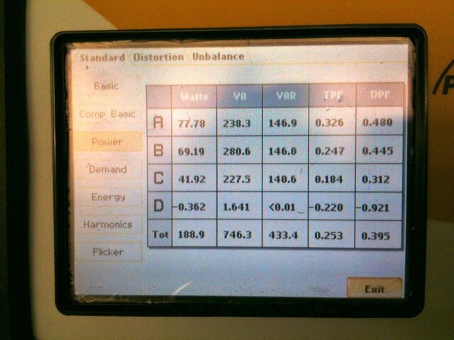
A77.78238.3146.90.3260.480
B69.19280.6146.00.2470.445
C41.92227.5140.60.1840.312

35%
PhaseWattsVAVARTPFDPF
A138.4330.8204.40.4180.570
B142.1363.6196.90.3910.558
C105.5317.4198.00.3320.487

50%
PhaseWattsVAVARTPFDPF
A229.7419.3244.70.5480.680
B238.3439.9228.70.5420.713
C198.2399.4236.90.4960.641

75%
PhaseWattsVAVARTPFDPF
A384.5520.5255.40.7390.830
B394.0527.5226.90.7470.866
C353.0492.3244.30.7170.822

100%
PhaseWattsVAVARTPFDPF
A557.0601.4165.90.9260.958
B567.1602.0116.30.9420.980
C526.2568.8149.70.9250.962

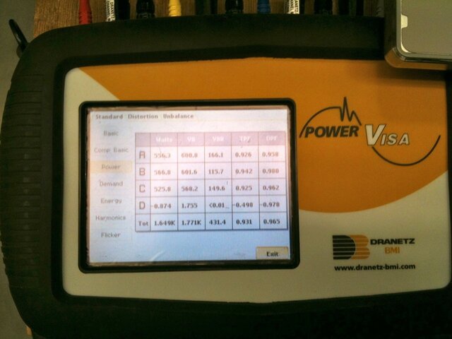
And here are a couple of pics from the meter. Meter.jpg 20 Percent.JPG

Now we do have this still setup so we can provide other data if desired including phasors, harmonics graphs, etc. It's a nice meter and fun to play with. And why do we have it? Well, from time to time we run into odd power issues on job sites so we decided to station one meter here and one in the UK. We have them packaged with instructions and can leave them in place for a period of time to even gather anomolies and glitches. Then, people on site can email us the files and we can analyze them here. Technology is cool.

Ok, so how are we feeling about the data?

David
 
The setup:

Sensor SR12+ with CEM+
Configured with Linear curves and no regulation
3 Source Four PARs with 575W lamps
1 PAR in a dimmer on each phase
3 Phase power feed at 120/208V
SmartFade console
Dranetz PowerVisa 440 [remembered that wrong this morning] Power Analyzer with 4 voltage probes and 4 CTs with ground ref tied in at power feed to rack.

We recorded readings with all the dimmers running to the same levels - 20%, 35%, 50%, 75% and 100%. We also ran each dimmer individually, but saw the same readings on each phase as with all dimmers running to the same levels, and therefore did not record them.

20%
PhaseWattsVAVARTPFDPF
A77.78238.3146.90.3260.480
B69.19280.6146.00.2470.445
C41.92227.5140.60.1840.312

35%
PhaseWattsVAVARTPFDPF
A138.4330.8204.40.4180.570
B142.1363.6196.90.3910.558
C105.5317.4198.00.3320.487

50%
PhaseWattsVAVARTPFDPF
A229.7419.3244.70.5480.680
B238.3439.9228.70.5420.713
C198.2399.4236.90.4960.641

75%
PhaseWattsVAVARTPFDPF
A384.5520.5255.40.7390.830
B394.0527.5226.90.7470.866
C353.0492.3244.30.7170.822

100%
PhaseWattsVAVARTPFDPF
A557.0601.4165.90.9260.958
B567.1602.0116.30.9420.980
C526.2568.8149.70.9250.962

And here are a couple of pics from the meter. View attachment 7578 View attachment 7579

Now we do have this still setup so we can provide other data if desired including phasors, harmonics graphs, etc. It's a nice meter and fun to play with. And why do we have it? Well, from time to time we run into odd power issues on job sites so we decided to station one meter here and one in the UK. We have them packaged with instructions and can leave them in place for a period of time to even gather anomolies and glitches. Then, people on site can email us the files and we can analyze them here. Technology is cool.

Ok, so how are we feeling about the data?

David

Excellent! It might be nice to add the data for THD-sub-I, just so we can all make that harmonic current correlation with the PF numbers.

ST
 
Thanks! Also not to go one question to far, but what happens with a sine wave dimmers?

Edit:
Can anyone explain why the switch causes the voltage and amperage to be out of phase? And also why at 100% does there still seems to be a reactive power load? If (in theory) your not chopping the sine wave doesn't that mean part of the cause of the var is else where? Or is it just close enough that it doesn't matter?
 
Last edited:
Thanks! Also not to go one question to far, but what happens with a sine wave dimmers?

Edit:
Can anyone explain why the switch causes the voltage and amperage to be out of phase? And also why at 100% does there still seems to be a reactive power load? If (in theory) your not chopping the sine wave doesn't that mean part of the cause of the var is else where? Or is it just close enough that it doesn't matter?

Typical phase control dimmers cannot turn completely on, so there is always a few microseconds of zero-crossing dead-time. This creates a slightly non-sinusoidal current waveform, which accounts for the PF of less than 1 when the dimmer is as close to full as it can get.

ST
 
Thanks! Also not to go one question to far, but what happens with a sine wave dimmers?

Sine wave dimmers work by sectioning the waveform into many slices at a high frequency, much like meat slicer does in the deli. The output sections (or slices) are evenly spread across the waveform so that the output waveform still resembles a sine wave. Because the peak of the flowing current is not shifted towards the end of the waveform as it is in phase chop dimmers, the sine wave dimmer has a much higher power factor that does not change with the dimmer setting.
Sine wave dimmers also get rid of a few other problems, most notably, no triplen harmonics. Also, because there is not one BIG chop, RF harmonic issues are not a problem either. From a power standpoint, the whole thing is almost as clean as an autotransformer! ... Only one problem left. Price.
 

Users who are viewing this thread

Back