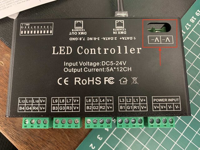
RGB LED Tape DMX decoder wiring

Palms

Member
Hi all,

I have a DMX decoder for RGB LED tape and I want to wire it up for use on a show. Its clear how the tape gets wired in but I have got a bit confused on how the power supply hooks up. There is an in for the power input clearly marked but then there is also another 'V- V-' terminal that I'm not sure what I need to do with. I purchased it online and the wiring schematic is also a bit confusing. Pictures attached hopefully show what I mean.

Any help much appreciated.
 

Attachments

  • DMX decoder.jpg
    DMX decoder.jpg
    518 KB · Views: 361
  • IMG_8529.jpg
    IMG_8529.jpg
    322.3 KB · Views: 671
I'm wondering if that's just a take off for running extra "ground" - you could try just ignoring it and connecting your tape to the labelled outlets, or just link both the V- tags to the V- on your input as per the schematic.
 
I would follow the directions and come out of your V- and up the the ones in the back.

That is weird though. Maybe the Chinese engineers were drunk that day and didn’t feel like running negative traces to the other side of the PCB 🤷🏻‍♀️

Or

Maybe it’s just an alternative spot to run your negative leads. Which seems silly as you would want them all on one side. Who knows.

Hook it up though for sure.
 
Hi all,

I have a DMX decoder for RGB LED tape and I want to wire it up for use on a show. Its clear how the tape gets wired in but I have got a bit confused on how the power supply hooks up. There is an in for the power input clearly marked but then there is also another 'V- V-' terminal that I'm not sure what I need to do with. I purchased it online and the wiring schematic is also a bit confusing. Pictures attached hopefully show what I mean.

Any help much appreciated.
This is very odd. The reverse would make more sense. Your V+ is going to take more load than any of the V- so it would be useful if you wanted to use lower gauge but more wires.

This doesn't make much sense at all.
 
I won't comment on the probable quality (or lack thereof) of the gizmo.

I suspect the "main" V+ and V- connections on the load side of the unit are mainly for powering the control electronics. The two big V- connections are the return for the power from the LEDs. This is clearly a low side switcher--the positive power for the LEDs goes directly to them, not through the controller box, and then the return current has to go somewhere and the heavier terminals on the DMX side seem like the logical place for that to be happening. (Logical, in the sense that it's what makes most sense given the terminals and layout of the gizmo). There would be much more current on the negative supply lead than the positive supply going directly to the box in any case since the full LED current only goes through the negative power supply terminal connected to the box, and not the positive supply.

The wiring diagram they supplied doesn't look too confusing to me. The positive supply goes to V+ and to the LED tape common cathode, the negative supply to both sets of V- terminals. Even without understanding why it's done that way, logic suggests that one ought to follow it unless better information magically becomes available.
 
Just used that very same pack for a show. I ran a wire from the one side V- to the other, as per the schematic. It ran 4 16' led strips just fine. Dimming curve was decent - no visible stepping at the low end. Wish it had an Intensity channel in addition to the RGB, but we lived with it.
 
Ok I will bite. If for a given +ve load current, should it not match the -ve current?
In this senario the LED strip gets +ve hot and switches the -ve of each the RGB legs to allow the LED to light up in the prescribed colour.
Current cant simply disappear between the +ve and -ve terminals can it?

Regards
Geoff

You're absolutely right that the current doesn't just disappear; that's basically Kirchhoff's Current Law in a nutshell.

The +ve terminals on the box itself don't carry the LED current, just whatever is consumed by the control electronics in the box--which I'd guess is tens to maybe a couple hundred milliamps, most likely. The -ve terminals on the box must carry that current plus whatever current is going through the LED tapes, potentially quite a few amps worth. Hence the need for more numerous and beefier -ve terminals than +ve terminals.

It's possible, though certainly far from guaranteed or even all that likely, that the two sets of -ve terminals are electrically isolated from each other to a greater or lesser extent.
 
The short answer is the little screw terminals are only rated for 10 amps and you can pull a max of 60 so you need the extra v- to handle it.

There are two ways of hooking up the tapes. You can either connect all 4 leads to the screw terminals. So one power and a ground for each color. Or you can do it like show in your second image where the power goes directly to the tapes and just use the three ground for the colors.

The reason for the extra V- is that those screw terminals are only good for about 10 amps. No problem for the individual color (ground) channels because they are rated for 5 amps each. If you are going to pull more than 10 amps total from each RGB (3.33 amps a channel) then you would want to hook the tapes directly to power and not use the screw terminals. For the ground at max power 5 amps x 12 channels is 60 amps so you need the bigger connections.

A standard 60 led per meter, 12v tape will draw 400 milliamperes per color per meter. If you are using full rolls of 5 meters per channel. You get 400 ma x 5 meters x 3 colors x 4 tapes or 24 amps. You would fine using the v+ terminals and not having to run wire directly to your supply. Figuring that the terminals are only rated 10 amps minus the China derating of who knows. It would be best to hook up the extra v-.
 

Users who are viewing this thread

Back