Rudimentary Block Diagram Question

Roma V

Member
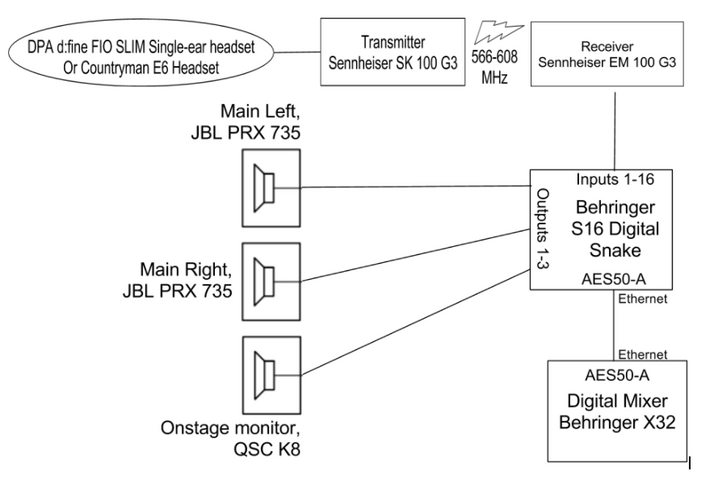
Hello! I am a high school senior and I have a college technical theatre interview on Friday and was hoping to show them how the sound system at my high school is set up. I don't really have any formal training, but I found information about block diagrams on the internet and thought it would be a good way to show signal flow in our space. I'm sure the diagram that I made isn't perfect, but I was wondering if it makes sense and is readable for someone with more experience than me. Below is the diagram that I made:

Screen Shot 2017-01-11 at 11.38.02 PM.png
https://docs.google.com/document/d/1J-fpusyU6--5CFY6j_nvP6UwhnKlApqq40igClQP9AY/edit?usp=sharing

Any feedback is helpful! Thank you so much!
 

Attachments

  • Screen Shot 2017-01-11 at 11.38.02 PM.png
    Screen Shot 2017-01-11 at 11.38.02 PM.png
    48.7 KB · Views: 2,308
Hello! I am a high school senior and I have a college technical theatre interview on Friday and was hoping to show them how the sound system at my high school is set up. I don't really have any formal training, but I found information about block diagrams on the internet and thought it would be a good way to show signal flow in our space. I'm sure the diagram that I made isn't perfect, but I was wondering if it makes sense and is readable for someone with more experience than me. Below is the diagram that I made:

Screen Shot 2017-01-11 at 11.38.02 PM.png
https://docs.google.com/document/d/1J-fpusyU6--5CFY6j_nvP6UwhnKlApqq40igClQP9AY/edit?usp=sharing

Any feedback is helpful! Thank you so much!

So far, so good. If you have more than one wireless mic you may indicate one of ten (for instance) shown,
You could also indicate how things are powered. Possibly your main left and right speakers are on separate breakers and you could show this. Basically you're off to a good start. In general terms, inputs are normally to the top and left and signal flow reads down and to the right although this isn't carved in stone. You could also indicate if your receivers connect into your mixer's inputs at mic or line level.
Toodleoo!
Ron Hebbard.
 
Pretty clear to me.

For future diagrams I recommend putting inputs on the left, outputs on the right, and keeping everything in a horizontal flow. What you have for this is fine but in a more complicated setup it's easier to become familiar with a new system when you can read the schematic like you would a book, left to right, top to bottom.

Probably doesn't matter for this but I also like to show each and every connection and label it as it is labeled on the device. For what I do, I need to be able to to look at schematic and see not only what I've already used up but which inputs, outputs, and ports I either forgot about or still have room to put to use. Sometimes my drawings are interpreted by someone experienced, other times wired directly off of by an installer who's not paying attention, and other times looked at by someone who knows nothing about sound systems. Heads a few things off at the past to trust the reader as little as possible and do as much of the thinking for them as I can by matching the labels and connections on the devices to what I'm showing on my drawings.

If the individual wires have labels printed on them, I also like to label the type of wire (Data, Mic, Line, Speaker, etc) with the wire number (WLS 1, WLS 2, WLS 3, ANT A, ANT B, SPK L, SPK R, so on). Lot of systems in the world with unlabeled wires and people get by just fine. Harder to get yourself into a position where something is patched wrong if the physical wires are labeled though and documented which one plus into which jack.

That's all pretty high level though. Most systems don't have schematics in the first place. Those that do tend not to be recently updated. Any amount of documentation however simple or complex is a step in the right direction so long as it suits your needs.
 
I suggest you split out the input and output connections from the digital snake to the sound console ... otherwise it looks like the digital snake is the central brain of your system and the console is just some sort of outboard processor. use arrows to indicate signal flow so people can follow the movement of the "sound".
 
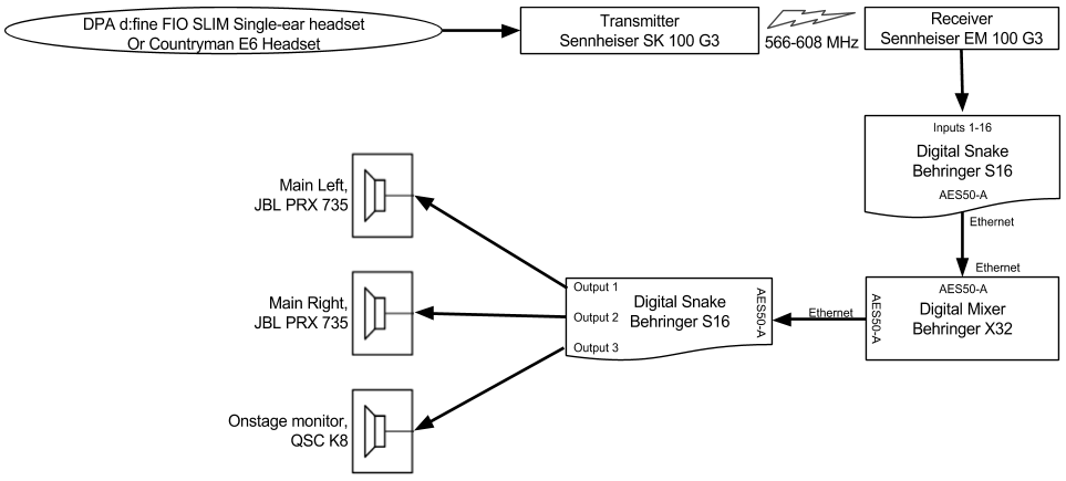
Thank you so much! I definitely think it would make the most sense left to right, I did it the way I did just to make it fit on one page and keep the font readable. I added arrows to show the direction of flow and split the snake up. Does it still make sense?
Screen Shot 2017-01-12 at 10.42.12 AM.png
 

Attachments

  • Screen Shot 2017-01-12 at 10.42.12 AM.png
    Screen Shot 2017-01-12 at 10.42.12 AM.png
    21.7 KB · Views: 1,037
It's definltely more clear how the signal moves through the system.

But it looks like you have two digital snakes now. Can you merge those together, maybe keep a dotted dividing line between the input and output sections of the snake so that it is apparent that this is one piece of equipment that handles both functions. Then you would have a more accurate depiction of the actual equipment in use.
 
Although they are powered speakers, I would still put some indication in the diagram that there is an amplifier in use.
When at all possible, you want to limit the flow of the diagram to "left to right." (Although this one is pretty clear.)
 
Although they are powered speakers, I would still put some indication in the diagram that there is an amplifier in use.
When at all possible, you want to limit the flow of the diagram to "left to right." (Although this one is pretty clear.)
Should I just add the information that they are powered speakers? They aren't connected to separate amps.
 
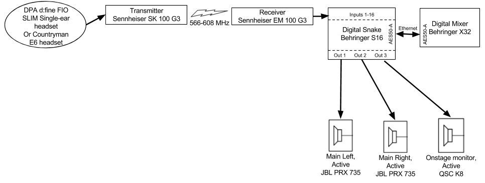
I tried to fix the flow to be more left to right (though I didn't fix it completely). I'm not sure if my change to the snake makes it look like not the brain. Thank you everyone so much for your input!
Screen Shot 2017-01-12 at 11.41.11 AM.png
Looks better to me.
Adding "Active" indicates they are powered so that covers it. Usually, when I end up with a block of white space, that's where I insert a table and text to fill in any missing info.
Gives it a more balanced look ;)
 
Just as future reading, you should take a look at the USITT Sound Graphics Recommended Practice. It discusses and gives examples of how to create a System Block Diagram. The USITT Sound Commission page has the Sound Graphics Project (which gives the recommended practice) as well as examples of different sized systems.
http://www.usitt.org/sound/

While a bit of a tangent from the original question posed, I only know one or two professional designers who follow all of USITT's graphics standards. They are for sure a good baseline, and a helpful starting place in designing a personal drafting style that works for your workflow. The general consensus is that the standards that they have proposed are very limiting on large-scale sound systems - a system designed by academics for academics without thought to real world application. There is no way to look at a plate and quickly pick off information in a quick fashion.

Most folks add a handful of simple colors and different line types in order to differentiate different types of signals - consider that in a sound system I might run two dozen different types of cables there needs to be some way to differentiate them. Even the same type of cable may do a half dozen different things (Cat5 can do dozens of things, i.e. I'll run a data network, Dante Main, Dante backup, Aviom A-Net, Video Balun over Cat5 in the same system). Colors and various dashed lines go a long way.

I generally have two different classes of flow as well - a proper full-scale line flow of the entire system on a single plate, generally done in a program like Vectorworks or Omnigraffle where I can toggle on and off layers to add/reduce complexity at will when I'm troubleshooting, and a second set of smaller flows, done on the backside of all my physical rack drawings that show me the flow inside any rack I may need to work on. Generally it's a bit more graphical and basic so that I can hand it off during the building process to people of various skill levels and they can pull off all the data they need in order to build.

As for the original question -- check out the USITT's small non-musical sound system, it's the perfect starting point.
 

Users who are viewing this thread

Back