Vintage Lighting Self Sustaining Carbon Arc

I would bet leather as well, but it could be doped with something to make a better seal. Could even be a metallic powder / oil mixture. Or, it could have accumulated a coating from rubbing in the cylinder. Things were not too exotic back then, but age may have changed their composition to something that is hard to recognize.

It's something. Not lead - too light for that - but similar in scratch test. Not aluminum - too dull and different in scratch (when was aluminum invented anyway?) Soft, but similar in color to lead or better yet molobium like magnets. New test tonight... It's conductive! Multimeter in Ohms' test easily passed test from side to side of the pneumatic cork with a breather slot. Not brass or bronze, and given the cylinder is brass - not picking up color from it.
 
Ship, An AC arc's carbons will burn at the same rate, are usually the same diameter, and will have similar-appearing ends after they've burned for a while. A DC arc will burn its positive much faster than its negative (the trim may have a 20"x3/4" positive and 12"x1/2" negative), the positive will form a definite crater (round, if the carbon rotates) while the negative will form a sort of rounded pencil-point. Most of the light will come from the positive crater, which will usually be pointed at the reflector (in a projection lamp or follow spot.) Old AC/DC arcs will usually have same-size carbons either horizontal in front of a reflector or on a vertical diagonal in front of the reflector.

I got a chuckle out of the nameplate--"i on 110V, 2 in series on 220V". Some years ago I worked on a picture in a steel mill. We got our power from the overhead crane rails which were 250VDC. (Couple feeders with ends "C"-clamped to the rails.) All the arcs (brutes & 150s) were wired in pairs from spider blocks. Two stagehands on each pair--both strike together and opening as simultaneously as they could. Inkies were in pairs, too, but that's another story.

Thanks for above in re-conforming how it was wired given both 1/2" rods and one shorter. Possibly last use DC before it was dropped. Posts/carbons didn't check before removal as with wells. One broken in removal - the lever to release was thoroughly seized on both. So story of fixture seems at last at this point, it fell over at some point in a bad way - at least once. Parts of the arch mechanism were repaired I'm told by the welder - yet to find where. Caster rivets were 2/3 broken in a lot of scraping along a floor with them not working. Cover to the arch mechanism was in thin metal cracked and at one point repaired as with gel frame area in a corner. Main problem in perhaps someone semi-skilled in making these repairs was that possibly what caused the caster rivets to break also caused the ceramic cores to the resistance coild to also break in making wire resistor coils perhaps short between. This was not addressed.

It was fixed at some point before of after the last dropping of it. Assuming I can fix the resistor coil ceramics, than re-twist the resistor coils around them, A lot of work and attention but this thing might work again!
 
Ship, Rebuild your resistor(s) carefully. I suggest repairing the ceramic core(s) as well as possible, then G-E-N-T-L-Y un-twisting the resistance element (I would assume it's a coiled coil) just enough to slip the core inside it, then G-E-N-T-L-Y tighten it up and fasten it. That heavy Nichrome wire is usually brittle and VERY hard to splice if it breaks. May be best to take a resistance reading now while it's in one piece, in case replacement is necessary.
 
Resistor cores I think easy. In this case three single windings, ceramic core I am absolutely sure I have figured out how to repair. Have been very careful with the coils and should slip in just fine. Feeding the attachment wires thru he ceramic on both ends will be the most tricky but I'll be careful not to kink while doing.

Photo showing cast bronze/brass (Negative/Neutral) lever arm verses cast iorn lower arm. While I didn't want sand blast it, Shop Manager was all about get this rusty... out of the shop, and given it's going to be attempted to work, I did have to replace most of the insulator pads etc. But because of sand blasting, I revealed something important to know about the arms and how it was wired. Taking the project slow in a little more epoxy to the cover hood repair on the flanges, further grinding than paint of the reflector. High temp. silver did not reproduce what the reflector was, so I had to use some chrome than dulling spray on it. Looks about correct now, hopefully the paint will survive a fixture test if it gets that far.
 

Attachments

  • IMG_20180928_212136592.jpg
    IMG_20180928_212136592.jpg
    88.5 KB · Views: 130
Fixture head is done. Just finished high temp. ceramic glueing up the broken ceramic supports for the resistor coils in the ballast area. Hopefully the glue sticks - will know in 24 hours.

Still a slight mystery on how the electromagnet part of it works with the adjustable stop.

Hot wire comes in thru the bottom of the fixture thru an isolated terminal and goes directly to the exposed bracket for mounting the carbon rod. This bracket is carefully isolated from conducting to it's support arm. All isolators & wiring replaced, all parts re-surfaced and hopefully back to spec. Not sure why the silver paint was applied to all of the working gear side ?help in isolating in power? I didn't re-apply it, but did do a few coats of lacquer on all but terminals just in case & to preserve.

Neutral comes into the bottom of the fixture thru an isolated terminal & goes directly to the lower wire of the solenoid coil and exits at the top of the solenoid coil. It than feeds thru the top isolated bronze carbon arc arm to the cabon bracket & carbon. The working arm of the solenoid / electro magnet is not connected directly to Line (hot) power but is connected to the mechanical gears, weight and pneumatic shock absorber. There is no continuity of the solenoid arm to hot or neutral, but there is to frame.

In theory, when the rod gets too short, one leg of the "W" shaped center rod of the electromagnet touches the stop plate - also connected to frame. It than in theory shorts to the non-grounded isolated frame in ?providing a high resistance thru the neutral? This breaks the arc and shuts it off (given the lower arm carbon mounting bracket and it's lever to lock it in are still live.)

Make sense in the best of my understanding? The frame of the fixture becomes a big resistor to current flow on the neutral side in breaking the arc. The theory is premised though on the concept that the lever arm of the electromagnet does not have to be attached to anything for return path of current. It just floats up/down dependant on the length of the carbons. Starting at the longest rod position, it also starts at the most open position. As the carbon rods burn away, the electromagnet senses resistances to current flow and somehow adjusts the electromagnet inner core to adjust with the gears so as to bring the rods together a little more. You start the arc touching by the way & the electro magnet separates the arc but brings it back to the proper balanced arc distance. The pneumatic cylinder is just a shock absorber to slow down the movements of the electromagnet. Once the rods get too short, one leg of the W' shaped moving core of the electro magnet shorts to frame in causing more resistance to current flow on the neutral side. Once this happens, the arc is broken and current stops flowing.

Did I get this concept correct?
 

Attachments

  • IMG_20181007_185540760.jpg
    IMG_20181007_185540760.jpg
    304.4 KB · Views: 152
  • IMG_20181007_185533067.jpg
    IMG_20181007_185533067.jpg
    285.6 KB · Views: 126
  • IMG_20181007_185522214.jpg
    IMG_20181007_185522214.jpg
    295.3 KB · Views: 125
  • IMG_20181007_185513074.jpg
    IMG_20181007_185513074.jpg
    293.1 KB · Views: 124
  • IMG_20181007_185500668.jpg
    IMG_20181007_185500668.jpg
    290.8 KB · Views: 130
Last edited:
Next up, While I took photos's of the resistor core (Ballast), I was not able to note if it was hot or neutral run thru the resistors. That much less why the third resistor core was not attached. I remember noting from above that DC operation would eat away at one more carbon than the other, and this was the case. Re-checking my notes on the ballast wiring but if anyone knows, also help.

Getting close, just the resistor cores to re-install (carefully) & wire, than buy some new 1/2" (Carbon rods - one broke & would not want to use other than new anyway given the age, heat and oils used to try to un-sieze the mechanisms.) Have some 1/4" in stock but definitely want the 1/2" for this.

Growing a little worried about the testing if it works though honestly. Granted I would do a remote switch, and plan to at least add a vinyl insulator to the carbon rod mechanism levers.. but if something I missed in inspection, or if say doing two of three coils as found in use.... that could be it. While a lot of people at work and on-line want to see it in operation... I'm Swinging towards finishing the wiring in restoration and not striking it's arc. If it fails, it can never be repaired. Just a concern and thought though... So many people are interested, I'll probably strike the arc. Me, kind of like all projects, I don't really have an emotional attachment to seeing the end result - more the process and onto the next project - getting out the door a 1909 carbon arc followspot w/o ballast.
 
Last edited:
Ship, I'd vote for leather piston washers, too. Worked pretty well if kept oiled. As to the reflector, it may have originally been polished and then painted with some metallic paint after it dulled. Have you tried to remove a tiny spot of paint somewhere to see what's below? And if so, what did you find?

Black base under silver I think part of the primer coat or paint in reflector. Think the black was added after finished silver fixture to outer areas. In sand blasting, left just enough area not-blasted to show silver paint as found. Interesting silver spray, but doubt I could replace & other than dirt & silver & rust, no indications of a different coating above on the reflector. Not to say perhaps, but in this case beyond I think what I can do unless an idea of how for the reflector.

To me it seems as if black based or primer to all with silver paint applied overall. Than once fixture gears housed up, black paint applied to all but reflector. Wiring etc. were also black.
 
@ship: Looks like a very nice restoration job! I'd love to see it working--please do get some video if you get it running and if you can.

Yes, a mechanical feedback mechanism. The springs try to get the arc to shorten. ) As the arc shortens the current increases. As the current increases the solenoid attempts to lengthen it. As the arc lengthens the current decreases. The process repeats. The "shock absorber/dashpot" (with the mystery washer) dampens the oscillations that would other wise occur. I'd bet there are stops for the movable carbon holders that prevents the arc from burning the carbons down to nothing, preventing the arc from burning off of the carbon holders.

When you're ready to fire up you might call the local National Carbon distributor--they used to and may still carry arc carbons.

A long (l-o-n-g!) time ago I worked for a firm which rented surplus W.W.II anti-aircraft searchlights for advertising purposes. (Among a lot of various other advertising 'specialties' but that's another story.) (We did a lot of business every fall at new car model time.) The lights were 150 amp DC arcs mounted in 5' daim. parabolic reflectors and produced a parallel beam. Each light was trailer-mounted with a following trailer carrying the generator. Both positive and negative carbons were power-fed by a motor drive, the negative carbon drive being geared from the positive carbon drive through a gear reduction to compensate for the slower-burning negative. There was a little lens which focussed an image of the positive carbon crater on a bi-metal strip. As the positive burned off and the image moved the drive motor would advance the positive carbon until it image was back on the bi-metal which would then open the circuit to the positive drive motor. The positive carbon also rotated (another drive motor) to keep the positive crater round. A trim (10"x5/8" negatives and 22"x3/4" positives as I remember) burned about 1-1/2 hours. All in all nice lights to run, providing everything worked as it was designed and the genny didn't run out of gas!
 
Thanks for the reply, your interest in part helps to just do it & taking the video, even if not sure it will work infailing in a way bad. Electrically and mechanically it sounds all good to you in main concern from the above understanding of how it operates? Stops physically are there in arms bottoming out, but was thinking that was the purpose of the electromagnet stop plate - before it got to that point. Though your point is now taken, such a stop plate stops it mechanically not electrically perhaps as thought.
 
Last check for the night before bed, 006 ohm's resistance in each resistor coil once fresh surface was filed for. Appears to be a 14ga wire. No continuity short of filing. Does this help in figuring out the resistor coils - two or three should be used to sustain a 25A arc on 120VAC? Beyond my ability to know and a major concern..
 
@ship, is that 0.006 ohm or 6 0hm? (Look at https://en.wikipedia.org/wiki/Nichrome) Nichrome's resistance increases slightly w/temp. But a 6 ohm resistance would carry 20A at 120V. To suggest to be safe the first time around, connect the arc light in series with, say, a 2kW or so incandescent. This will prevent the magic smoke in the event that anything in the mechanism shorts. You might be able to strike an arc with this series setup but it would be pretty weak and may not be able to maintain. If everything looks OK, remove the series lamp & try it on a 120V 20A circuit w/out the lamp in series.
 
6 ohm and thanks for the idea and concept!

That was with one of the resistors, there was two interconnected - both bottoms of the resistors connected to power terminal... still studying if hot or neutral but probably hot, and bridged at the top of the resistors in feeding the fixture head. If Understanding you and learning, the resistors bridged still has 6 ohm's resistance overall - even with two. Both of them just adds capacity - in why the other resistor core I worked on was a double coil wound. But why not the third resistor coil connected? Also assuming given electrode wear, this was seemingly last used as DC... adding to the question of the third coil necessary for AC?

Answer perhaps... try it with 2x coils and the 2Kw lamp, than with three connected. Than try it again w/o the lamp in series. Thanks for educating what is above my head.

Good news! Ceramic high temp. epoxy stuck to all three resistor ceramic winding supports! They are all repaired (above photo's of what they looked like.) I did not stress them too much but am designing a sub-base to the casters which will spread the base firtjer and prevent falling over again - much less not stress the 2/3 broken casters. I can now wire up the resistor core/ballast & in theory have a working fixtgure. Noting above the 2Kw lamp resistor in making me feel a little more safe about powering it up. Thanks!
 
As I understand your explanation there are two, 6 ohm resistors and one "double-wound" resistor. When you say the two 6 ohm resistors were "bridged at the top" do you mean they were connected in parallel? If their resistance was 6 ohms each and they were in parallel, the combined resistance would be 3 ohms but the current carrying capacity would be doubled. A circuit running from one side of the line, to one side of the arc, then through the arc, then through the 3 ohm resistor, then to the other side of the line would, when the arc is struck, conduct 40 amps at 120 volts. It's possible that the unit was/is a 40 amp arc. ( How big (diameter) are the carbons? And are the two carbons the dame diameter?)

It's also possible that the third resistor (have you measured its resistance?) was originally able to be switched into the circuit to reduce the current & dim the arc.

When you fire it up, definitely do connect the 2kW lamp in series. This will limit the current to 18 amps (on a 120V supply) no matter what the arc lamp is doing.

I can't tell from your photos; how large is this unit? (Height & side-side & front-back?) What are the dimensions of the reflector?
 
Well, 40 amps as the arc was struck, but once there was voltage drop across the arc, the current would drop. Lets say the arc was dropping 35 volts. At 110 volts line, that would leave 75 volts across the resistor which would then have a current pass of about 25 amps.
As for the third resistor, it may be that things had to be reconfigured depending on the source being AC or DC. I would suspect the two modes did require some reconfiguration and possibly a different trim set. After all, AC and DC arcs are very different.
 
I just looked again at the first photos you posted, in particular the nameplate. "25 Amps at 110 Volts, two in series at 220 volts" The 6 ohm resistor would be correct. I don't see the three resistors in your photos--where are they?
 
As I understand your explanation there are two, 6 ohm resistors and one "double-wound" resistor. When you say the two 6 ohm resistors were "bridged at the top" do you mean they were connected in parallel? If their resistance was 6 ohms each and they were in parallel, the combined resistance would be 3 ohms but the current carrying capacity would be doubled. A circuit running from one side of the line, to one side of the arc, then through the arc, then through the 3 ohm resistor, then to the other side of the line would, when the arc is struck, conduct 40 amps at 120 volts. It's possible that the unit was/is a 40 amp arc. ( How big (diameter) are the carbons? And are the two carbons the dame diameter?)

It's also possible that the third resistor (have you measured its resistance?) was originally able to be switched into the circuit to reduce the current & dim the arc.

When you fire it up, definitely do connect the 2kW lamp in series. This will limit the current to 18 amps (on a 120V supply) no matter what the arc lamp is doing.

I can't tell from your photos; how large is this unit? (Height & side-side & front-back?) What are the dimensions of the reflector?


Start over, each of three restistors were 6ohm.l Was referring to a past ballast about double coil. Yes two of three current fixtures are bridged in parallel and one not in use - though keep in mind one electrode was shorter than the other.

Carbons are 1/2"(+ not measured but certainly not 3/4 or even 5/8) and slightly largerer in not measuring. Same dia. of the carbons - though one shorter when found. This on the above name plate is rated at 25 amps AC/DC. I will measure the existing carbon and the broken ones. Otherwise we are thinking as I am if I understand, the line voltage feeds thru the resistor coils if I understand correctly. We have gone thru a lot of work up to this point and thanks by the way.
 
You're welcome (for whatever I've said that helps!) Two same-size carbons seem to indicate a light designed primarily for AC use. Even 'way back when' people knew that the positives burned faster in DC arcs. When running this arc on DC, yes, it would run, bu it would bur positives faster than negatives, so the arc would move out of the focal point of the reflector if left burning for too long. (Maybe for film use with short takes this didn't matter.)
 
Interesting concept and yes in no means to regulate the arms different.
 
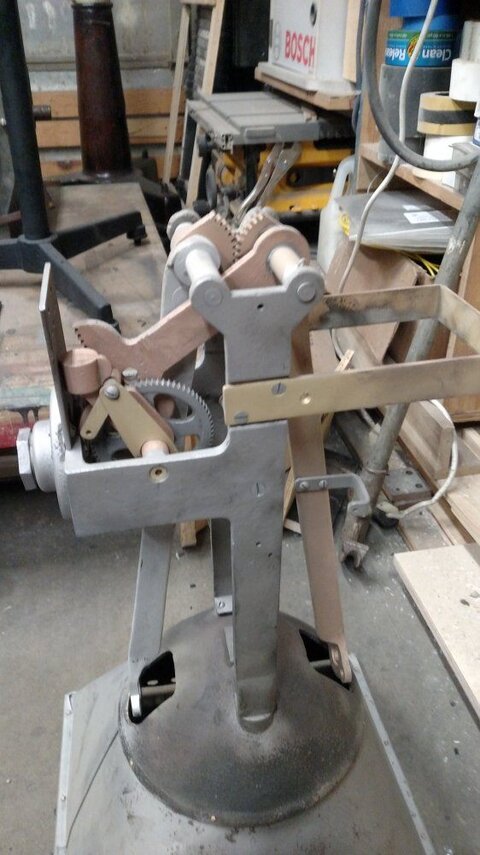
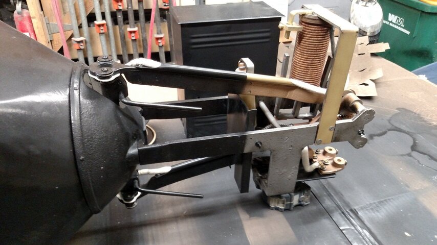
Fixture head is wired & ready. TBD, insulating the carbon rod levers & getting two new carbon rods. After sand blasting it’s cover, N / H were marked so that made it easy to determine the electro magnet & arch stop mech. was running thru the neutral.

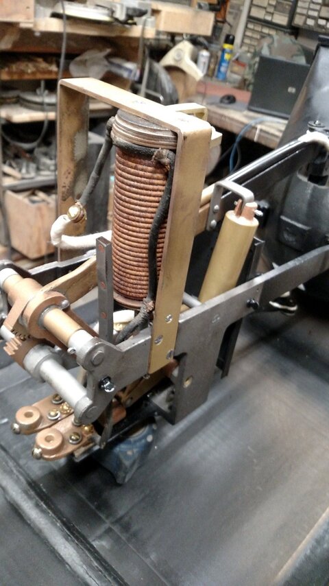
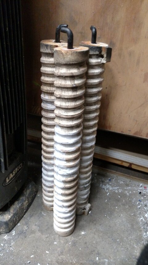
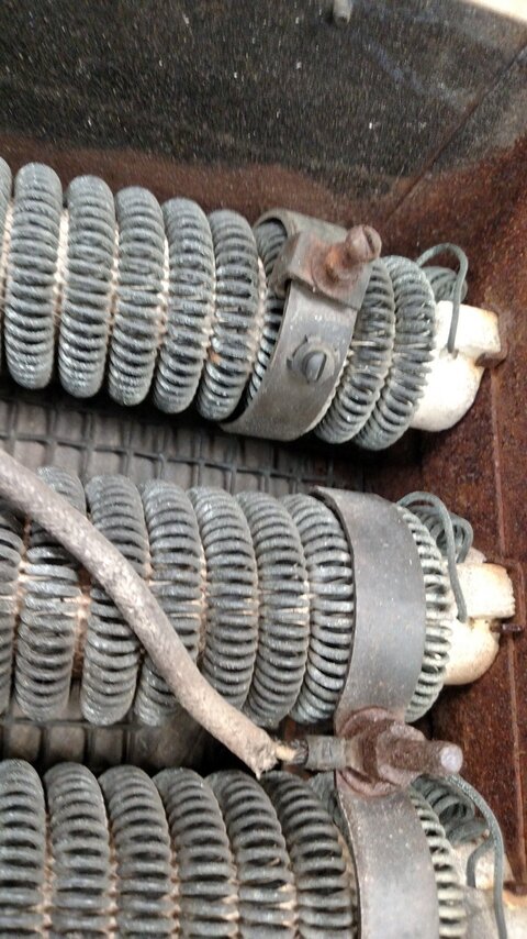
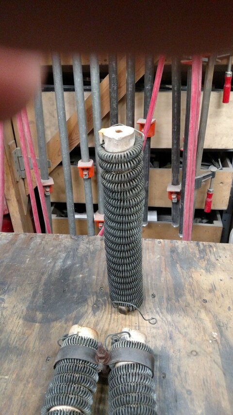
Resistor core onto wiring now. I finally got the 
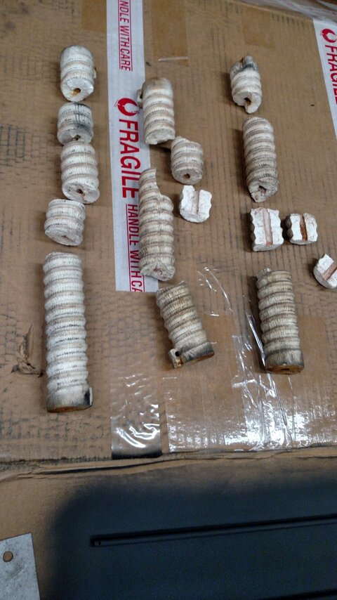
porcelain coil supports to glue back together - only one core broke in half as I was re-coiling the resistor spring to it. Was able to stretch the spring out enough to glue & clamp it back together. All cores are now at least self supporting in holding them horizontally. Should be fine given they live vertical and at most only has to work once.

Thought I took enough photos, & given it’s been weeks since I started the project - especially this part I took apart first.... A few problems are coming up in the pre-wiring of the resister core.
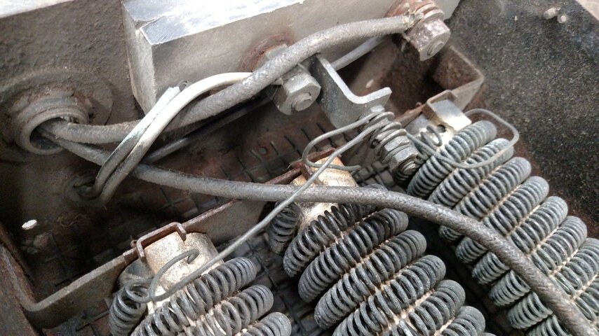
First, the plug 3-conductor non-NEMA open faced plug that was somehow grounded to frame. Photos indicate it’s grounded thru the first asbestos isolation block mounting near the center of the fixture. It is using 12/3 type S cable so brittle and cracked, (rated for 20A - not 25A) you can literally pluck the outer jacket off the cable with a finger. That said, the cable and grounding probably isn’t original. Very early say 1950 or earlier, in even if really old, I don’t it’s the original cable feeding the fixture. (Grounding for a AC/DC fixture?) Given the brass braising repairs to the light fixture, probably earlier than the 40's when last attempted to use - after it fell over, or perhaps post after it fell over and broke the porcelain resistor coils.

Will it now grounded become a problem given some sort of shorting to frame theory of in not grounded and the fixture head assembly not being grounded and it’s stop mechanism somehow getting more resistance? Or does this grounding answer the question of current flow in how the stop mechanism works? Don’t know.

Second, While very oxidized in conductor color, I believe the hot wire goes direct to the lower asbestos block terminal, than up to the lower arm. This by way of what is left of wire coloring in photo - that which is not covered in carbon arc dust. And in trusting the above re-wiring conductor colors. Was it correctly re-wired at least a half century ago? The resistore core box was missing it’s cover which might have had stamped H/N indications on it (or not). Had to make a new resistor core cover. Given the evidence, the hot leg of power feeds directly thru the resistor core, to the fixture head and its electrode. The neutral conductor does all of the electromagnetic work and resistor core work. That sound correct?
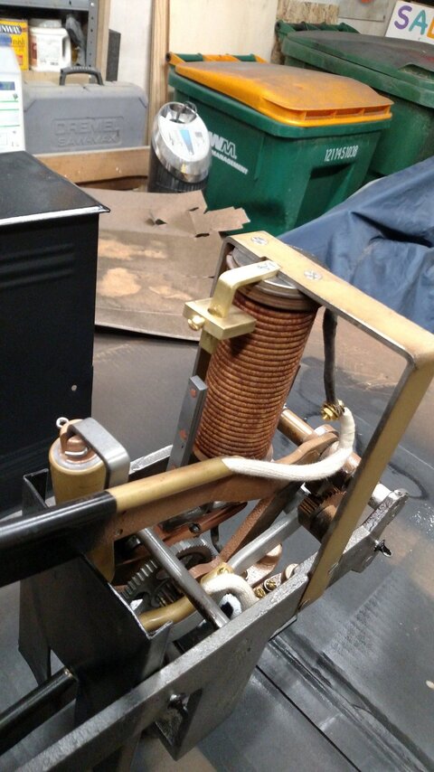
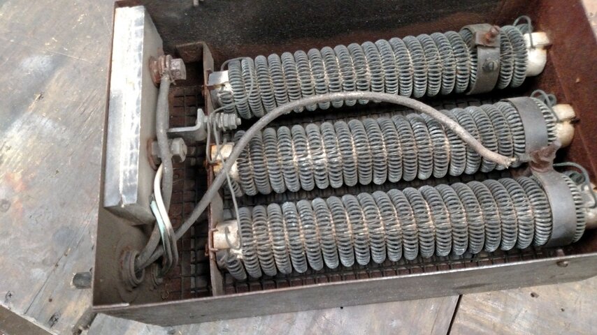
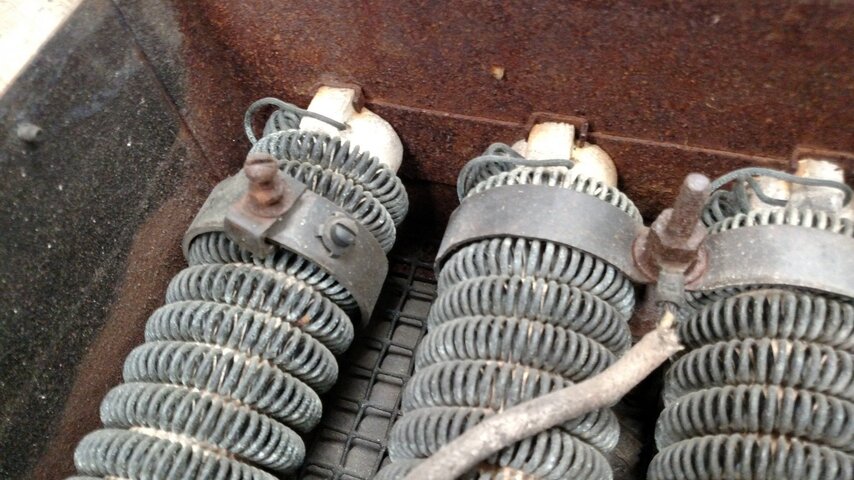
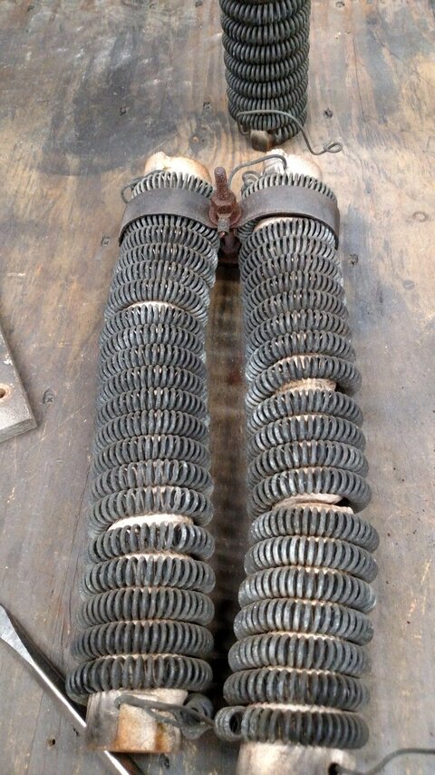
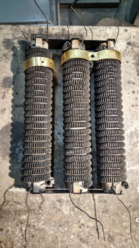
Third, Given the neutral line to the fixture head attaches to the above dual copper brackets of the coil, what’s going on with the like +6" long upper part of the wire not used? I simply do not remember what this upper conductor was doing, but it’s long enough to be doing something. Almost appears as if this wire were shoved down into the resistor coil spring - but that doesn’t make much sense. Cannot see anywhere on the frame they were attached to. Being they are resistors/heater coils, do they contact back to the hot I’m not seeing in photo and some connection I am forgetting about? Believe I only see a Line in, Line out to fixture head connection, but perhaps on that outside to the left 
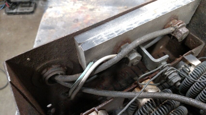
terminal block it has another connection to all of these conductors? That’s something important I missed, and something I don’t understand completely yet.

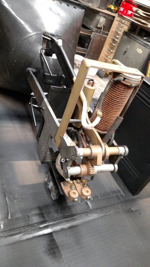
I note in the 6th photo, there are 4 solid conductors under the terminal.... that's interesting.
 

Attachments

  • IMG_20180904_202753608.jpg
    IMG_20180904_202753608.jpg
    373.3 KB · Views: 102
  • IMG_20180904_202804390.jpg
    IMG_20180904_202804390.jpg
    275.5 KB · Views: 100
  • IMG_20180904_202829824.jpg
    IMG_20180904_202829824.jpg
    360.3 KB · Views: 103
  • IMG_20180904_202836167.jpg
    IMG_20180904_202836167.jpg
    397.4 KB · Views: 97
  • IMG_20180904_202943391.jpg
    IMG_20180904_202943391.jpg
    385.3 KB · Views: 100
  • IMG_20180904_211126937.jpg
    IMG_20180904_211126937.jpg
    432.4 KB · Views: 122
  • IMG_20180904_211131578.jpg
    IMG_20180904_211131578.jpg
    354 KB · Views: 117
  • IMG_20181014_211514502_HDR.jpg
    IMG_20181014_211514502_HDR.jpg
    496.1 KB · Views: 105
  • IMG_20180906_191322181.jpg
    IMG_20180906_191322181.jpg
    342.2 KB · Views: 127
All three resistors are wired to a common (the copper buss), so they could be connected three ways:

1. Two in parallel = 3 ohms
2. One by itself = 6 ohms
3. By adding a jumper wire, three in parallel = 2 ohms

Right now, it's wired for #1. I would start with it wired for #2, by moving the wire from the double, sliding tap to the single tap. Light it up and measure the current if it strikes and runs. If it won't strike and run, or the current is really low, you can switch to #1, which will double the current. My guess is #2 may have been to run one light on 208/240 Volts. It just seems unlikely that they would have used combination #3 because 2 ohms seems way too little. Also, I doubt they would have designed it to need a jumper added, because it would get lost.

The sliding taps allows some adjustment to the current, burn rate, and brightness. More current by moving it toward the common.

I would wire the incoming hot wire to the terminal that goes to the resistor common. That will allow the resistor to act as a current limiter if the thing shorts someplace else. I would connect the resistor tap wire to the lower carbon arm. I would wire the incoming neutral to the solenoid coil, and the other side of the solenoid coil seems to go to the other carbon arm. (?)

That would put the all of the components in series, making the circuit as follows:

hot > 6/3 ohm resistor > carbon 1 > arc gap > carbon 2 > solenoid coil > neutral

The incoming ground should connect to the chassis and outer, metal case for safety.

Wire connected to the resistor tap needs to be high temperature.

After it is all put together, ohm out or hipot test from the hot and neutral to chassis ground. It should be open (infinite ohms). With no carbons inserted, the circuit from hot to neutral should measure open.

Do the carbon arms touch without carbons inserted? If not, then no shutoff mechanism is needed because it'll simply quit when the carbons get too short.

I would test this thing with a fused disconnect switch, with a 30 A, time delay cartridge fuse in the hot line. That will give you a beefy switch and short circuit protection. Use plenty of PPE, goggles, gloves, burn and melt resistant jacket, etc. It'll probably work fine, but safety first.
 

Users who are viewing this thread

Back