Transformer Question

derekleffew

Resident Curmudgeon
Senior Team
Premium Member
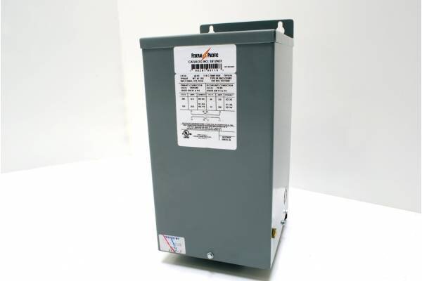
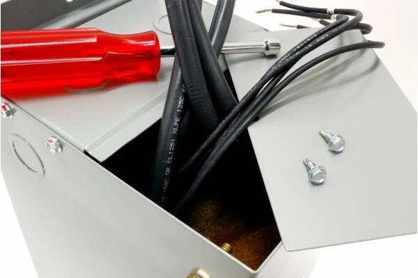
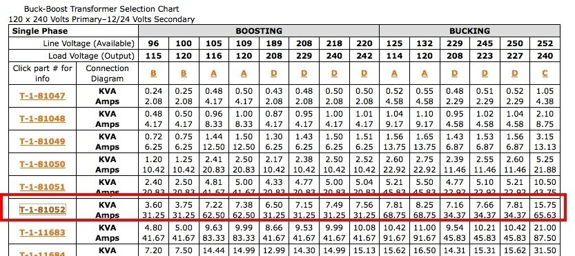
An installation currently has two effects projectors and wishes to add a third. All three projectors are 240V. The two currently in use have this transformer Model T-1-81052 Acme AT1471 - Buck Boost Transformer - 120 x 240 pri - 12/24 secondary - 0.75kVA , to boost the voltage from 120 to 240. The transformer is identical to this one, and the core is potted, with just the eight wires coming out.
4057-transformer-question-federal_pacific-sb12n.750f-transformers-1.jpeg-s-20100924110826-w-600-h-400-t-.jpg

4058-transformer-question-federal_pacific-sb12n.750f-transformers-4.jpeg-s-20100924103659-w-600-h-400-t-.jpg

Unlike in the picture, on mine, all the wires are the same guage.

There is no 240V service anywhere convenient.

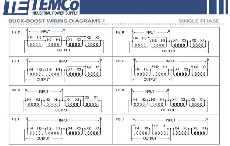
So I bought an identical transformer, ACME T-1-81052 Primary: 120X240, Secondary: 12X24. It has eight wires labeled H1, H2, H3, H4, X1, X2, X3, and X4. How do I connect the inputs and outputs to make this go from 120 to 240?

I tried looking at how the others were wired, but the genius who installed them some years ago cut off or removed the wire labels. I know this transformer is sold as a buck/boost, and is often used to step up 208V to 230V. None of the wiring diagrams provide for what I am wanting to do, but I know it can be done as the other two do exactly that.
4059-transformer-question-acmebuckboost.jpg


4060-transformer-question-buckboost-diagram.jpg


Oh, by the way, in case anyone is thinking Consult a Professional Electrician, (normally very prudent advice), I did, and his suggestion resulted in 64V output when I input 120V. So I'm hoping [USER]STEVETERRY[/USER], epimetheus, Dionysus, et al can help me.
 

Attachments

  • Federal_Pacific-SB12N.750F-Transformers-1.jpeg?s=20100924110826&w=600&h=400&t=.jpg
    Federal_Pacific-SB12N.750F-Transformers-1.jpeg?s=20100924110826&w=600&h=400&t=.jpg
    10.4 KB · Views: 1,219
  • Federal_Pacific-SB12N.750F-Transformers-4.jpeg?s=20100924103659&w=600&h=400&t=.jpg
    Federal_Pacific-SB12N.750F-Transformers-4.jpeg?s=20100924103659&w=600&h=400&t=.jpg
    21.6 KB · Views: 1,180
  • AcmeBuckBoost.jpg
    AcmeBuckBoost.jpg
    159.2 KB · Views: 4,572
  • BuckBoost Diagram.jpg
    BuckBoost Diagram.jpg
    174.4 KB · Views: 12,518
Last edited:
A buck/boost transformer can't convert from 120V to 240V. That is why you don't see a wiring schematic for that need in the table. What it does is allow you to add or subtract a small amount of voltage.

I suggest you post a picture of the nameplate of your projector, or otherwise post its exact electrical requirements. If the projector simply needs 240V 2p3w, such as that delivered by a NEMA 6-20 connector, I believe you can give the buck/boost transformer 208V by using two phase legs from your 120/208Y system and boost it to 229V using the transformer you purchased. This is probably what was done with the pre-existing transformers and projectors. If you try this, though, make sure the projectors will work with 229V instead of 240V.

If the load requires a neutral so it can get 120V for control circuits, then the transformer you bought is not going to be useful. But since the additional projector and transformer are presumably identical to the existing ones, I suspect you won't run into this problem.

You will certainly have to change the electrical circuits feeding this projector, as you can't do what you want with a 120V supply unless you buy a different transformer. So you should find an electrician who is more capable than the last one to help you with this project.
 
Jeff, I understand and totally agree with what you're saying, except...
The existing projectors are plugged into circuits providing 120V via a NEMA 5-15 (Edison) connector via a DMX-controlled relay panel. The input is 120V, and the output is 240V, as measured with my Fluke 87-III meter.
 
The two primaries are identical, so you connect them in series (as an autotransformer) to double the voltage. You can add the secondary, if you need, for an additional 12 or 24V boost. Be careful to ensure correct phasing when wiring transformer coils together. It sounds like your electrician wired the coils correctly, but got input and output swapped.

boost_xfmr.JPG

/mike
 
The only thing about that style of transformer is; make sure those unused leads are capped nicely! Wish they came through with lugs.
 
Since I got a name drop, I guess I have to go ahead and reply...

n1ist hit the nail on the head. While not the intended usage of the transformer, it will work just fine. My preferred solution would be a transformer that has a 120x240V primary and secondary. Of course then you would have to have the appropriate OCP per NEC Table 450.3(B). The transformer you have, as you've got it connected, is field connected as an autotransformer, thus it's OCP should comply with NEC 450.4.
 
Desired result achieved. Sincere thanks to everyone who contributed. :clap:

Where are connection diagrams A and B?
To view these, one must click on A or B here. May be an entirely different set of connection diagrams, but I didn't look too closely as none of them had what I wanted.
 
Last edited:
I second the capping of unused secondarys! I was working on a exit sign, checking for power with a non-contact tester, when my hand brushed against the unused 277V INPUT. Let's say it was more than a tingle... Learn from my error and cap those wires!
 
More about wirenuts and the type of rubberized stranded wire on those transformers. Single conductors don't like to stay in the wirenut. Often, I see ballasts come through with heat shrink on the unused taps, which works well. Had to deal with a bunch of these transformers a few years back that were on a string of parking lot fixtures. Circuits were tripping off all the time. In each case, almost every one had the same problem, the tape dried out, the wirenut fell off and the conductor shorted to the case. (on unused taps) I cut the wire end flush, folded it over, and put a heat shrink sleeve over the end and applied heat.
 

Users who are viewing this thread

Back