The way the dimmers are wired is you have 6 individual breakers and 6 Individual Cards. For Single
Phase three breakers are tied together with a copper cutout that sits inside of the three
breaker contacts. That will give you 120V @ 60A for One Hot, then 120 V @ 60A for the other Hot
feeder. Or in three
phase it pairs two breakers onto each
phase for 40A /
Phase.
The feed from the
breaker is then terminated into a
block that runs the length of the pack. One feed off the
breaker goes directly to the
dimmer module to provide
power for receiving signal, another one feeds the actual dimming
circuit /
fixture. So each
breaker has two feeds coming off of it, one strictly for control
power, one for
dimmer (lighting)
power.
The neutrals off of everything
tie back to a
neutral bar so you have 6 neutrals from the lighting
instrument then one single
neutral from the controller.
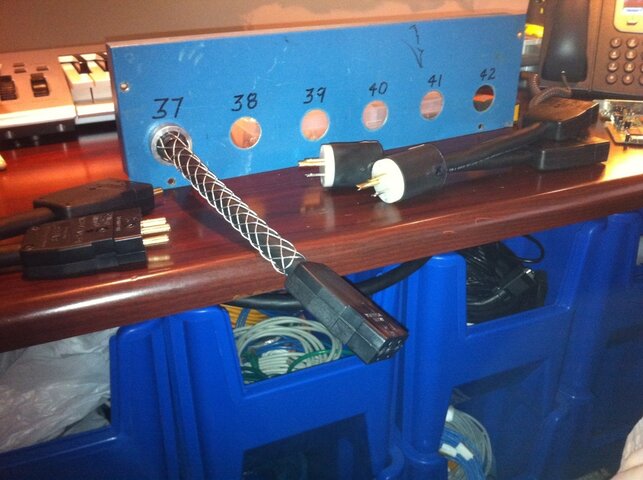
All the grounds are tied together from the
power connectors (
stagepin in this case), then terminated into a lug attached to the chassie.
Any who just an explanation for the above question as to how the device is wired.
----
To the topic at
hand however I think I'll just
wire a 40A
Twistlock 3
Phase onto it and
call it a day. Then for each
venue I'll have to figure out actual
power distro.