What is this?: Patch panel two-for-one

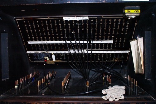
On the Ariel Davis system that I used in high school, (1957-1959) we had a very interesting patch panel that had chassis mounted male and female connectors, that were a single pin or socket about 3/8" in diameter. To patch you would use a cable that had a male connector that also had a female connector on the back of the male connector. It had a cord coming out the side of this multigender connector, and at the end of that cord was a female connector. The dimmer outputs were the chassis female connector and the load circuits were the male chassis connectors. You would plug the cable into the dimmer output and run the cable to the load circuit. Then you could piggy back as many cords as you like on the back of each other, running each cable to a circuit. But then again, the lighting instruments were plugged into "Stagejacks" the predecessor of the stage pin. Also we had plano-convex fixtures instead of Fresnel. OK, old timers, I am waiting for I remember older systems than that.

Tom Johnson
 
A venue I worked in used to have an Ariel-Davis slider patch panel. It sure made it easy to two-fer. Too easy. It could result in major dimmer overloads as the slider passed through an active circuit on it's way to a new patch.
3948d1192911570t-patch-panel-ariel-davis-slider-patch.jpg
 
My first "patch Panel" was the jumper cable size alligator clips on the portable salt water dimmer system that I ran for my mother's March of Dimes presentations for Polio circa '54 - '55. The "dimmers" were 1 quart, long neck, milk bottles in a wooden case 'kinda like a one sided beer or pop 6-pack. The Web/handle on one side became the "back" of the unit. The web had vertical slots in line with each bottle. A wood peg with a bolt and a captive spring slid up and down in the slot. The end of the bolt had a bare copper wire that could be dipped in and out of the bottle. Each bottle had a small copper plate at the bottom and an insulated wire connecting it to the power. The closer the wire to the plate, the brighter the light. The Alligator clips went to the lights and I don't remember how the circuit was connected back to ground or neutral. I was very young then and did not know the terms hot - neutral - ground etc, just plug it in here and put the clips here and move the sliders. Different world then. Can you imagine a mother today letting her kid run bare wire electrical stuff? Back then, nobody thought a thing about it. Course then we didn't have child seats, seat belts, bike or cycle helmets, fall protection or outriggers on Geni lifts. Different World.
 
Late to the thread, I know...
Anyways, I know of these "telephone" type dimmer patch plugs, but never really understood how they work. It looks like the plug has a brass tip, but shouldn't it have two connections for hot and neutral, almost like a 1/4'' mono audio plug? (aka "guitar plug")
 
...It looks like the plug has a brass tip, but shouldn't it have two connections for hot and neutral, almost like a 1/4'' mono audio plug? (aka "guitar plug")
The plug only patches the "Hot" wire. All the neutrals are already tied together, whether used or not, so they're already patched where they're supposed to be.
 
Here's the one at the Athenaeum theater in Chicago. It's still in use.


I love the toasted area at the lower left! A reminder that patching is only to be done when the dimmers are down. Almost every patch bay I've seen had a few "user scars" on it ;) Somewhere in my back shed lies an old patch bay. As for the 20 amp limitation, many of those old connectors could only fit a number 12.
 

Users who are viewing this thread

Back