The acoustical consultant gave us a
riser diagram that I am having trouble understanding.
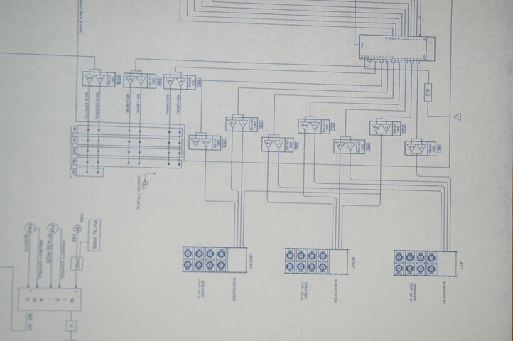
That actually looks like a single-line or functional diagram, a
riser diagram usually shows physical rather than signal routing.
I am assuming that the unlabeled 12x20 box is some form of matrix
DSP and that this is a
LCR system. I also want to preface my comments by noting that it is not
clear if these are schematic design, coordination, bid or construction drawings. If schematic or coordination drawings it may be that not everything has been finalized or detailed yet and many things may be clarified or changed prior to creating bid or construction documents. And while some things in the drawings may not make sense based on just the information provided, there may be valid reasons behind what is shown that is simply not
clear with just this information as a reference.
My questions:
1 - Do I really need three woofers?
Yes. If you were working with a separately derived
subwoofer signal, such as an aux
fed sub, then you would not need one sub per
array but a
LCR system with each
array being full range should have the same response from each
array.
2 - It looks like I have one amp ( model 502) driving one
woofer - and the other driving two woofers. Any idea why it is set up this way?
This is where it would really help to have the matrix
DSP outputs and/or
speaker inputs labeled to indicate the intended function, I'm not actually sure which outputs and amps are associated with the
subwoofer, LF, LF/MF and HF signals and drivers. I think the drawing may be a
bit confusing where they appear to show two
channel outputs from the
DSP, e.g. 1/2, merging into a single
line, that's not necessarily wrong, just maybe not as
clear as it could be. However, the drawing also seems to show 14 outputs from the
DSP feeding arrays that require only 12 signals. And I'm not
clear what is happening with PA1 and PA2, the drawing appears to indicate two channels out of the
DSP going into a bridge
mono amp, which may explain the apparent two extra outputs from the
DSP.
Based on the quantities of each amp (2 bridge
mono CX502s, 2 two
channel CX702s and 3 two
channel CX1102s), one might assume that the CX502s drive the subs, the CX702s the HF and the CX1102s the LF and LF/MF. However, that may not be accurate. If it is, the only reason I see to have one CX502 driving two subs is cost or rack space. Driving two 8
Ohm subs in parallel off a bridge mode CX502 would not be my first choice as the 4
Ohm rating for a CX502 in bridge
mono mode is at 1kHz and 1%
THD versus 20-20kHz and 0.1%
THD, indicating the amp is being pushed a
bit at that load. I will say that if I were to parallel anything between two arrays it would probably be between the left and right arrays rather than the right and center arrays as is apparently shown.
3 - Each
line array seems to take three lines in addition to the
woofer. One from a 702, and two from an 1102. Why do I need three lines for each
array? Why different
amplifier types?
The ILA WL2082i mains are a quasi
three-way box. There are two 8" drivers that both reproduce LF content but typically only one of the two drivers is used to reproduce mid frequency content. This can be addressed either via
bi-amp operation and the 'shading'
switch on the speakers or via
tri-amp wiring and external processing. The latter is recommended for best performance and seems to be the general approach being applied. Thus sub, LF, LF/MF and HF signals being run to each
array.
4 - The 1102s driving the right and left speakers are split. IE PA3 is driving Right and Left as is PA4. PA6 is devoted to the center
speaker. Any ideas why he did not just show PA3 as driving the left
cluster, and PA4 driving the right?
As far as PA3 and PA4, I assume that these are for the LF and LF/MF drivers in the left and right arrays. Since the LF and LF/MF drivers are the same drivers you could either run the left and right LF off one amp and the left and right LF/MF off another as appears to be shown or the left LF and LF/MF on one amp and the right LF and LF/MF off the other. I agree that it would seem to make sense to have it the same for all three arrays.