
DuckJordan
Touring IATSE Member
your misconception is you considering it volume after amplification, this is not the case its volume before amplification, its the incoming signal being adjusted not the signal leaving the amp.
.... But either way. My only problem was because the amp volume was nearly off..and the amp treble was all the way up.. That's why it would squeal so quickly.
...And painting Do Not Block signs on the floor in a rectangle around the breakers, dimmer rack and amp rack so I am not climbing over mountains of sets. ...


It's not an intimidating sign, it is simply stating a code requirement. I would be cautious about intentionally misapplying such signs, it could be a red flag to an inspector. It might be better to use more vague language in those situations.Oh, nice. Haha, we have a storage closest that people like to go into, Maybe I will put a similar sign on the door
And yeah those signs would be helpful too, The other day I was going to turn the amp off and I was walking on a mattress, boing, boing.
I love intimidating signs
Check your local electrical and fire codes. Each jurisdiction will be a little different. For example, in British Columbia, it is 1 Meter of clear space (39 1/3 inches).So it is 32 inches in front of electrical boxes right? Dont want to put up a false sign.
All our breakers and the dimmer rack is in a corner.
 I think what you've missed is this:
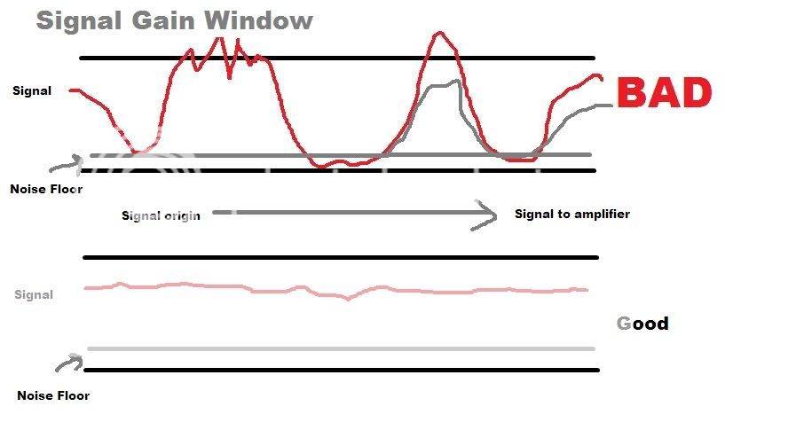
Every device in the chain from signal origin to the amplifier has the ability to boost or attenuate the signal. As has already been stated (somewhere in this thread), you want to keep your signal at a level so that it is well above the noise floor, but not so high that it clips. See picture...
This is what people were trying to convey to you.
I'm not sure what the lower black line is but I took the upper black line to be the maximum signal level, or the clip level, and the idea being to show that you want your signal between that maximum and the noise floor. I think the difference may be that it appears the intent was for the diagram to reflect the path through the, you are not seeing the signal waveform but rather the signal level at different points in the system. Perhaps more like the signal level diagram at the bottom of http://www.yamahaproaudio.com/products/mixers/mg32_24/pdf/MG32_14FX_block_level_diagram.pdf.
In that case it makes the point but is very simplified compared to a real system where the you may have the equipment noise floor and maximum level varying at different points and multiple steps of gain and attenuation affecting both the noise floor and the signal level.
We use essential cookies to make this site work, and optional cookies to enhance your experience.