
You are using an out of date browser. It may not display this or other websites correctly.
You should upgrade or use an alternative browser.
You should upgrade or use an alternative browser.
Vintage Lighting 1920s Lighting Controls?
- Thread startersross01986
- Start date

Now that's a lighting console. Before they tore down the highschool here they had one just like that from the 60's all over it were warnings written on and DO NOT TOUCH SPARKS! warnings all over. A lot of them had broom sticks tying stuff together.
It'll be interesting to see what the next iteration of lighting control is and see who's laughing at us and our desk consoles.
It'll be interesting to see what the next iteration of lighting control is and see who's laughing at us and our desk consoles.
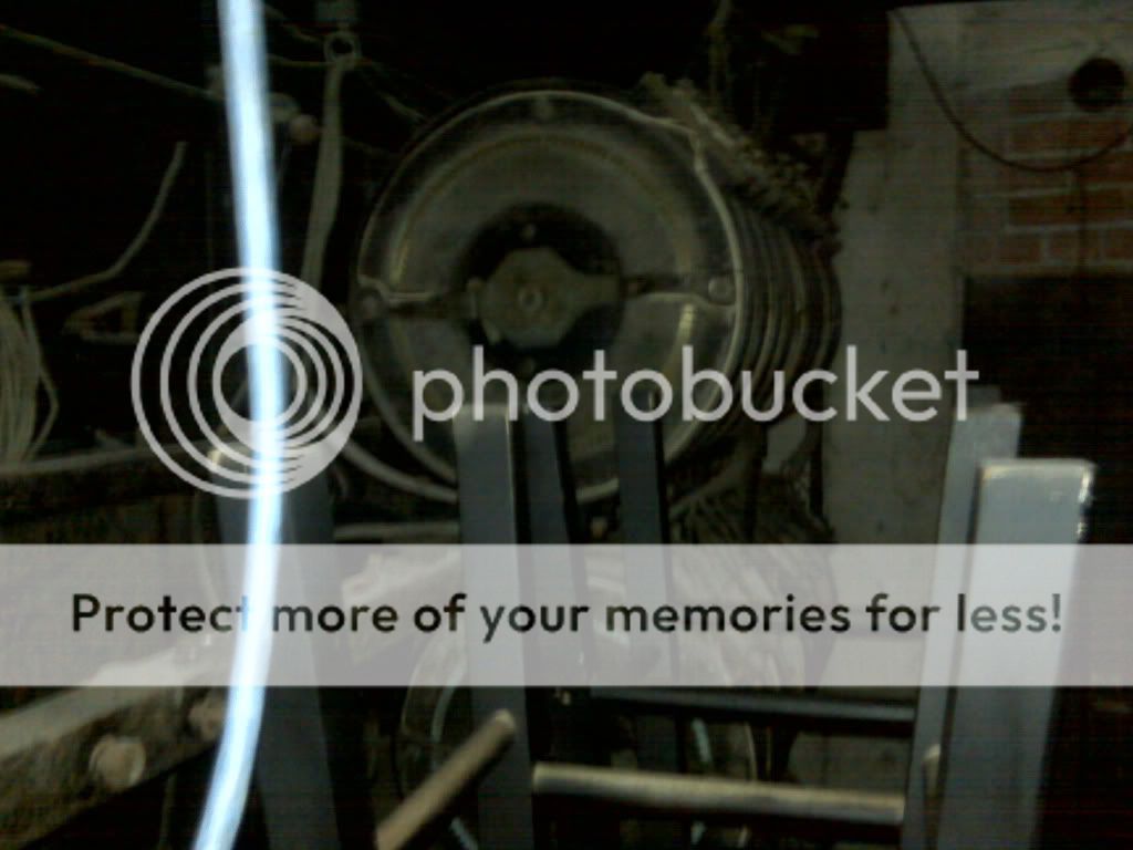
What's the big red wheel for?
Probably house lights. Often it's a whole bunch of resistance dimmer plates ganged together on a geared wheel. Lot's of loading on house lighting, thus multiple dimmers needed, bit only one control "handle". Hard to do anything under about a 20 count, on the system I worked once.
jstandfast
Active Member
What's the big red wheel for?
Grandmaster. It provides mechanical advantage (a.k.a. leverage) to move all the other dimmers.
Yup, 1950's 60's vintage. I remember these things very well. Probably auto transformers inside. If the slider on the transformer was not adjusted properly it would run off the end of the winding thus causing a loud snap along with lots of sparks at full load. Very entertaining. BTW, the door on the side is probably access to the 3 phase bus bar for the ablilty to connect auxiliary equipment. Ah the old days.Just so we're all on the same page here: it's understood that without regard to the title of the post, what is pictured is likely a product of the
1960's ?
+1 That's why you had a light crew instead of a board op. You actually had to have a touch for running one to make it look good.Yup, 1950's 60's vintage. I remember these things very well. Probably auto transformers inside. If the slider on the transformer was not adjusted properly it would run off the end of the winding thus causing a loud snap along with lots of sparks at full load. Very entertaining. BTW, the door on the side is probably access to the 3 phase bus bar for the ablilty to connect auxiliary equipment. Ah the old days.
jstandfast
Active Member
I think I'm with SteveB about the big red wheel. All the mastering handles(the long black ones) seem to be in the normal places for this kind of board,
and the big red wheel doesn't seem to be in the same plane with them, mechanically. We'll leave aside how much the red wheel would be in the way of an actual operator............
and the big red wheel doesn't seem to be in the same plane with them, mechanically. We'll leave aside how much the red wheel would be in the way of an actual operator............
Dionysus
Well-Known Member
The Highschool I went to still has one installed and in occasional use for one of it's Gym-stages. Looked into replacing the whole system, they just can't get enough money. Even had a museum offer to buy it.
I used to have some good photos (including some of me running it), however they were on the external hard drive I had stolen a couple years ago. Huge piss-off.
You really do need a feel to run it well, and have to keep in mind when doing the patching how much load is on each circuit and how much you can put on each of the dimmers (as each is a little different on it, especially being so old).
We called it "The Dinosaur" or "The Franken-Board" among other things. There are some dimmers that are totally fried and taped off, and some dead circuits too.
If I remember correctly this particular one was installed in the late 60s.
A lot better than a few buckets of salt-water
I worked at the Fox Theatre in Atlanta in the 90's and their original board from 1929 was still in operation for the house lights (such as they were) and the sunset effects on the ceiling of the house (an amazing piece of technology for its time).
It was easily three time the size of the board in the picture and its master wheel would crank all of the submaster and dimmer handles. As Steve noted, a three count was out of the question!
I wish I had pictures of it but that was back at the dawn of the digital camera age.
It was ultimately retired in late 98 right before I left. However I am sure they have kept it in place given its place in the history of the building and the organizations commitment to preservation.
Paul
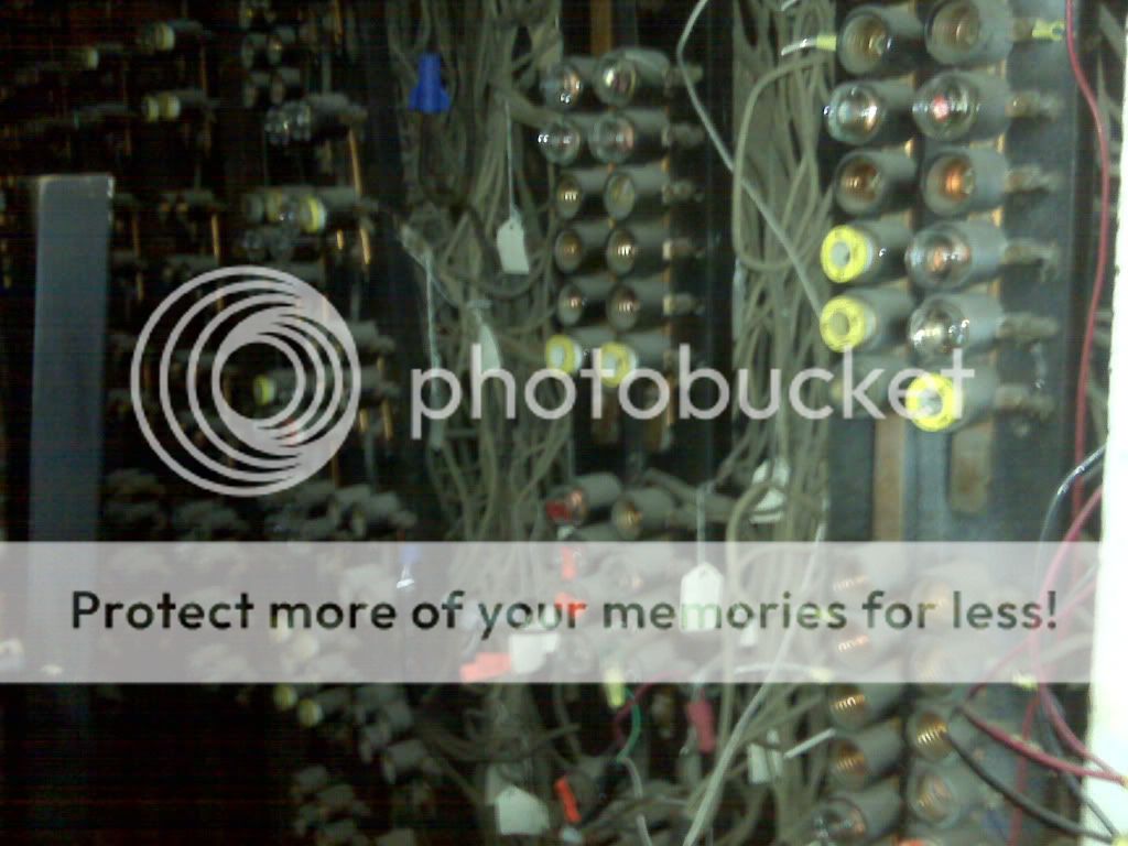
Several years ago I spent two days in the Orpheum theatre in Wichita, KS re-rigging their movie screen. This was the lighitng system that was partially still in use. Its the original lighting controls that were installed in 1922.
Wish these were better... it was several years ago and taken with my blackberry in a very dark corner of the theatre.
Wish these were better... it was several years ago and taken with my blackberry in a very dark corner of the theatre.


I would love to have an autotransformer board in our auditorium like the first one pictured. It would be handy to use as a backup, for focusing, or for setting the folks straight that think all you have to do is press a button to have a perfectly lit show!
Last edited:
JD
Well-Known Member
Several years ago I spent two days in the Orpheum theatre in Wichita, KS re-rigging their movie screen. This was the lighitng system that was partially still in use. Its the original lighting controls that were installed in 1922.
Wish these were better... it was several years ago and taken with my blackberry in a very dark corner of the theatre.
Wow! Cool! (or actually, very Hot) A resistance plate dimmer! On those, you had to match up the load exactly. If it was a 2k plate, you had to have a 2k load, or it wouldn't make it to black. (Thus, lots of extra fixtures in the basement lighting up the floor to make the numbers right.)
What I remember about those was Heat, Heat, and more HEAT! The autotransformer boards were a great leap forward because you could under-load them.
The Coronado Theatre in Rockford, IL had the presence of mind to keep their old controls when they ripped them out, and they put them on display in a side lobby. Most people dont notice them, or dont realize what they are and walk right by, but when I first noticed them I definitely did a double take. Its nice that they appreciated the history and nestalgia of the equipment to put them on display. I will look to see if I happend to take a photo or two, I'm not sure though cause this was a few years ago now.
Hence the term and reason for ghost load....(Thus, lots of extra fixtures in the basement lighting up the floor to make the numbers right.) ...
Not quite; there was some leeway. Exactly how much leeway, I can't recall....A resistance plate dimmer! On those, you had to match up the load exactly. If it was a 2k plate, you had to have a 2k load, or it wouldn't make it to black. ...
In high school, I think we put 750W on a 1kW, and 1500W on a 2kW single-plate dimmer, resistance. We only had 750W lamps, and I didn't know what a ghost load was back then. I don't remember NOT dimming to zero.
I wrote in the wiki entry ghost load that a dimmer had to be loaded to 75% of its capacity. However,
From Dimmer, Resistance - ControlBooth :
Later the same article states:
which would be 83.3% of capacity.Typical ratings of these dimmers [the two common sizes of piano boards: 14x3K, 12x6K] were 2500-3000W and 5000-6000W.
So it's either 75%, 80%, 83.3%, or some other %. Anyone know for sure? I believe one of my old textbooks contains the mathematical formula; I'll look it up if no one can answer definitively.
Last edited:
JD
Well-Known Member
So it's either 75%, 80%, 83.3%, or some other %. Anyone know for sure? I believe one of my old textbooks contains the mathematical formula; I'll look it up if no one can answer definitively.
Depends how much of an idle you can live with. At 100% load the lamp was black. At 80% you probably had a red filament. 20% number has to be an error as the light would be on quite a bit! After all, it was a big open ended variable resistor. The brightness was set by dividing the voltage going to the lamp up based on the ratio between the lamp resistance and the plate resistance. At 50% with a proper load, half the energy was lighting the filament and the other half was being turned into heat in the resistor.
There is actually an old lighting book I have somewhere that deals with the math. The low end "squelch" was aided by the fact that filaments drop in resistance as they near the cold state. This may explain why some under-loading was ok. (cold lamp would be "relative" as tungsten does not start its resistance climb until about 600 degrees F)
Following is from a 40 year old chunk of memory: A 1000 watt load is a tad over 10 ohms lit. To squelch the light, you need to have approximately 10 times the resistance in series, so a 1000 watt plate should be 100 ohms. At it's lowest setting, the lamp resistance drops to 1 ohm, so you have about a 100 to 1 ratio, or 1.2 volts across the lamp.
Likewise, a 2k plate would be 50 ohms, etc.
Are you sure that wasn't suppose to read "Within" ? (In other words, 80%)
Last edited:
Similar threads
- Replies
- 21
- Views
- 2K
- Replies
- 0
- Views
- 599
Users who are viewing this thread
Total: 1 (members: 0, guests: 1)