What's wrong with this picture?

millamber

Active Member
This was an install I was supposed to energize for a church. The electrician who did it refused to take my word about why he couldn't leave it like this, and insisted that he was right. It took a phone call from the manufacturer to explain it well enough to get it fixed properly.
 

Attachments

  • iphone 144.jpg
    iphone 144.jpg
    130.4 KB · Views: 565
Wow...

That's not at all how that's supposed to be installed. Kirk or Steve (from ETC), do you know if this is even legal?
 
from a carpenters standpoint i would fire this electrician, not only is that completely wrong but his workspace is horrendous. personally i feel that if your work place looks like crap then you work like crap. it tells me a lot about a person when i see them work and they end up being horrible.
 
It looks like it is still being worked on and until the rack is commissioned by ETC you don't need to worry about it. From what I remember, every time an ETC rack it turned on for the first time and ETC rep has to be there.

Who cares what the guys work space looks like. If your work space looks like crap (as mine does when I am working) but produces good work who cares?
 
i guess i was assuming he was done, and a ton of tools laying everywhere to me seems a bad idea... this is coming from a carpenters standpoint. if i am working on a house and i see lumber and tools lying everywhere i can almost guarantee that there will be major problems with the house because of poor craftsmanship
 
Luckily, I caught this before he had finished wiring the DR12 cabinet. He was in the process of bringing in the load wires through the SR48 rack into the top LB.
 
What church is this for? I'm here in Atlnata, as well.
 
This was in South Carolina actually.
 
I can't even tell what's part of the install and what's spare materials... oh maybe that's part of the problem :rolleyes:
 
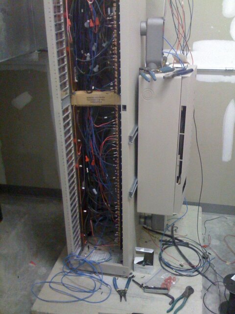
Problem I see here is why are there splices at all ?.

All wiring should terminate directly on the dimmer lug. If there are multiple outlets being energized from a single dimmer, the splicing should be elsewhere, preferably on a terminal block in an exterior cabintet.

All wiring going to lugs should be neat and bundled, only long enough to reach the lug and there's really no need or desire for "extra" wire in the rack. One good reason is it interferes with air flow thru the rack.

I had the same issue with the electricians wiring my dimmer racks back in '04. I took them down to another Sensor that had been wired by one of our campus IBEW electricians, which was letter perfect and told them this was how it was to be done, it's in the spec's. The fixed all.
 
So did the electrician never read Sensor+ UL Rack Installation Manual.pdf, or wantonly choose to disregard?


Page 32. I'm sure there are other issues, but that's the most clearly visible.

Heh thats the first thing I thought of too when I saw the pic. All those Wire nuts. we just had Sensor + rack installed. I wish I took pictures now but if it were possible to be too neat and tidy our installer did it. just the oposite extreme of the OP's picture.
 
Wow this shows the need for a safety board. I didn't even notice this picture was up until the reorganization.

This is one of my favorite pics that resides on the "Wall of Shame/Fail" in Phone Support. (Yes we really do keep pictures of the good ones.) This shows all sorts of things going wrong at one time.

My favorite thing going wrong in this picture is the fact that the DR rack is mounted to the SR+ rack with UniStrut that was screwed through the sheet metal into the baffles of the side of the rack. Not entirely structural, but, [sarcasm]"hey, the conduit will support the entire rack weight right?"[/sarcasm]
 
Last edited:

Users who are viewing this thread

Back