Control/Dimming ETC Express 250 Macro Port

I was wondering if anyone could give me an example use or two for the macro port on the back of Express consoles. The manual seemed a bit vague to me. I would think it is for remote triggering of the macro buttons on the board (M keys). Possibly to allow precise triggering based on remote actions? Like allowing actors to trigger specials with certain physical actions? Avoiding even split second delays in cue-calling would certainly maintain the atmosphere of a show.

Not that I really have any use for it right now but it has always been a bit curious to me.
 
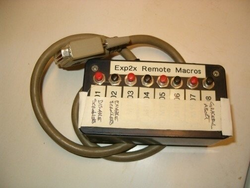
There are several things in that port. First, there are two relays. One that is normally open, another that is normally closed. I have used that relay to trigger things like mini disk players and other contact closure devices. It works great for that. The other thing in there is the macro ports. If I remember right, there is 6 of them. With that macro port you can do exactly what you described. Some of us have boxes sitting in the corner that has buttons on it to get to those macros. I have used that type of box for SM's to just have a go button or to control cue lights. Another thing it is useful for is interfacing with show control equipment. It really can be used for anything. I'm not really sure what drove ETC to put it in, but I am glad they did.
 
Ah that gives me all sorts of ideas then! Any chance you where I could procure the connector to make a breakout cable? I doubt ETC sells that directly right?

I wish I knew about that back in my own high school days. Here I was running special built lit-up-broadway signs for 42nd Street off the regular circuits. Come to find out that everything is dimmer doubled, so I was only running those lights at half brightness! Did seem kind of low.

With this I could have relayed a regular 120v outlet for them (with proper isolation of course). Ah **** hindsight.
 
I was able to pick that connector up at my local electronics store, I believe it's just a Male DB-15 you need (like this one), Yep just confirmed that in the manual, just don't confuse it with the 15 pin VGA that has 3 rows of pins, but comes up a lot more in a google search.

I used to use mine in gym when we set up for commencements so the facilities guys can turn the house lights on before we would come in (commencements here last 3 days of load in and rehearsals and 4 days of ceremonies).
 
Sorry I can't help you with locating a souce for the DB15 male connector needed to mate with the DB-15 female on the console.. We do not sell that connector directly, but should be available from electronic supply houses as BryanKacz pointed out.

To answer why this was initially implemented: several customers, including those in the theme park industry, wanted a way to trigger the console remotely after the show had been programmed. This was a solution to that need.

A word of caution, as it states on page 318 of the manual, this relay is for low voltage applications. It is rated for 30V 1A max. It is not intended for high voltage applications.
 
After you get the connector I don't understand how you control the macros. Do you have to make something with 6 buttons on it and you just assign those macors at the console? this sounds useful for me but I wouldn't know how to use it.
 
[EDIT: Express uses a DB-15 connector, thus a different pin-out, and only allows M1901>1904, but you get the idea.]

From the Expression3 user manual:
Installing remote macros
The console provides eight remote macro inputs through the 25-pin
connector on the back panel labeled Remote Go. A user-supplied remote
device connects to the console via a 24 AWG, aluminum-shielded, multiconductor
cable with one twisted pair designated for each switch (Belden
9507 S-R PCV Insulated or Alpha 5477 80 Deg. C 300 V PVC). The cable
connector at the remote device will vary depending on the device itself.
Console connector Remote connector
DB-25 female Connector type depends on unit
Pin Function
1 – Macro 1,901
2 – Macro 1,902
3 – Macro 1,903
4 – Macro 1,904
5 – Macro 1,905
6 – Macro 1,906
7 – Macro 1,907
8 – Macro 1,908
9 not connected
10 Ground
11 + 12 Vdc
12 not connected
13 not connected
14 +Macro 1,901
15 +Macro 1,902
16 +Macro 1,903
17 +Macro 1,904
18 +Macro 1,905
19 +Macro 1,906
20 +Macro 1,907
21 +Macro 1,908
22 not connected
23 Ground
24 + 12 Vdc
25 not connected

Wiring remote macros
There are three typical ways to wire the Remote Go function:
1. Connect all -Macro pins (pins 1-8) to ground (pin 10) and switch the
leads connecting the +Macro pins (pins 14-21) to +12 Vdc (pin 24) as
shown in the following diagram.
<wiring diagram omitted in quote>
2. Connect all +Macro pins (pins 14-21) to the +12 Vdc pin (pin 24) and
switch the leads connecting the -Macro pins (pins 1-8) to the ground
(pin 10).
3. Provide your own power supply that generates a 12 Vdc potential between
the +Macro and -Macro pins and switch either of these leads.
An old parallel printer cable, plus eight momentary switches and a box from Radio Shack, yields this:
RemoteMacroBox.jpg

Macros 1901>1908 can be anything one wants them to be, so that one is not limited to M1>M5 + M* on the console's facepanel.
 
Last edited:

Users who are viewing this thread

Back