Help wiring a custom fixture

duquesne

Member
So I'm building a lighting fixture that involves a bunch of bare 100w light bulbs. I've got 1.2k dimmers, so I'm looking to build several section with 11 100w bulbs. I want to wire them as a parallel circuit. What gauge wire do I need to use? The branches of the main line, can they be just regular zipline (they will go from the main to an individual 100w bulb). Also, do I need a ground?


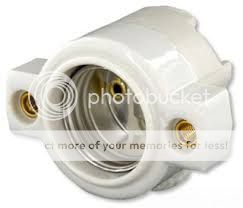
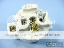
Here is a basic sketch(http://i.imgur.com/t1ARclL) (I messed up the neutral a bit on the link from the source to the first junction) and the sockets I have.(lights - Imgur)


I have the bulbs(cheap 100w from amazon), and have purchased a few sockets to build a proof of concept, but have not purchased any wire yet.


I'm usually a wrench jockey, this is all a little foreign to me. Any help would be appreciated.
 
The wire size is based on the breaker / dimmer size and the total load on the setup. Here is a chart below based on 80% capacity.

Gauge Amps Watts
#16 9 1080
#14 12 1440
#12 16 1920
#10 24 2880
#8 32 3840
#6 40 4800
#4 48 5760

According to your picture, Black is hot, narrow blade on the plug and brass screw on the socket, White is neutral, Wide blade and silver screw on the socket. Based on your dimmer size it should be a 15 amp breaker and you would use 14 gauge. That said if someone puts in a 150 watt bulb and plugs it into a 2.4k your will melt down. Therefore I would run 12 gauge wire to be safe. You can always over size

It is important that White/neutral is on the outside of the threads on a bulb so if a hand or finger touched it as it was screwed in it would not touch the hot circuit.

A ground wire is green and will be attached to the metal housing or raceway of a fixture or unit you are building. There is no ground screw on those sockets.

Wire nuts may not be needed depending on your set up as you could bare and loop the wire around the screw.
 
I posted this to another forum and was warned that the exposed terminal screws would be in violation of NEC Article 520. I've wired small things before and not thought twice about it, but never have I used this much juice. Do you have any experience with this particular code? Would liquid e-tape solve this?

As far as not needing wire nuts - If I loop straight onto the terminal screw, will it still be a parallel circuit? My designer requested that I wire them parallel, so that if one blows we don't lose the whole strip for the rest of the show. That's why I was using the wire nuts, to keep the main line separated from the individual branches.

Thanks for your help!
 
Those sockets (porcelain cleat sockets) can only be used inside an enclosure, due to the exposed terminals. What are you building? If it is enclosed (ie, sides, front, and back, so the terminals can't be touched with an ISO-standard finger), they are OK, but watch out for ventilation. Otherwise, you will need sockets that enclose the terminals. I just built one using these mounted thru the cover of a steel raceway.
These have enclosed terminals so they would be safe in the open. These may also work, but I would have to look at one closely to make sure there's no way to contact the terminals.

I would also be careful loading a 1.2k dimmer with 1100w. The inrush current may cause issues.
/mike
 
So basically what you're building is a strip light similar to a bathroom vanity fixture. Perhaps the best socket for this is the Leviton 9885 socket. It is similar in design to the one you have except that it has #8 threaded mounting ears where your terminals are, and the terminals are mounted on the back of the socket. It is designed to mount inside a trough or raceway so that the exposed rim of the socket is flush. The hardest part of constructing this would be drilling the roughly 1.75" holes for the sockets, as well as the small holes on either side for mounting, but making a cardboard pattern would make things easier (in addition to a good metal-cutting hole saw). They also make similar sockets with metal clips instead of mounting ears, but I find these to not be as secure, plus it doesn't dramatically decrease the difficulty of the build. The trough would also have to be built, but perhaps that could be outsourced to a sheet metal shop. Places that manufacture air ducting might be a viable lead on this. Unfortunately, no matter which socket you use, they will all need to be housed since the contacts aren't allowed to be easily accessed and the wiring can't hang freely.

The wiring is pretty simple. You'd need high-temp crimp on ring terminals, and they'd be wired like this (it is still a parallel circuit):

The ground would be bonded to the fixture's metal case. Note that the black and white dots represent screw terminals and crimped rings. No wire nuts needed, but some people will put a solder weld on each terminal after everything is tightened down. Essentially, your lengths of wire would only be as long as your socket centers.

I'd use #12 or #14 high temp fixture wire since the wiring would be enclosed.

Leviton 9885 (referred to as "keyless" sockets).


---

One other idea that came to me is mounting junction boxes along a solid structure and mounting keyless "garage-style" sockets to them. You can get them without pull chains. Then you'd just need to run conduit between each J-box. It would wire up the same as the diagram above except the grounding would be a little different. It would be easier to build using off-the-shelf parts, but the project would most likely be more expensive in the long run if you do it this way.
 
Last edited:
Update: The design has changed. In order to channel these according to the designer's plan I need to split these into smaller groups and use more dimmers. My two largest loads are now going to be 12 75w bulbs, and 9 100w bulbs. I'm going with 12 gauge wire to be safe. I'm also looking into different sockets. Unfortunately, I'm stuck with the ones I bought for my proof of concept, for those sections I will using liquid e-tape.

I'm looking into redesigning the mount. The show is in the round. There is a 4' wall behind the audience, with a 19"space between the fake wall and the real wall. These go on the ground there. They are safe from people, but their exposure is still concerning to me (some of the other staff do not seem as concerned). (imgur: the simple image sharer) This was my first small scale. If I had the sockets without exposed terminals, would I be able to do it like this?

I want to thank everyone again. I've done lots of small wiring (changing connectors, making a worklight with zip cord), but I've never made anything with this many lamps or this much juice.
 
I've done lots of small wiring (changing connectors, making a worklight with zip cord), but I've never made anything with this many lamps or this much juice.

For this reason alone you will want to make friends with a local electrician who will help you with the codes. It is not complex, but he will be able to give you the local information.
 

Users who are viewing this thread

Back