Vintage Lighting Self Sustaining Carbon Arc

ship

Senior Team Emeritus
Premium Member
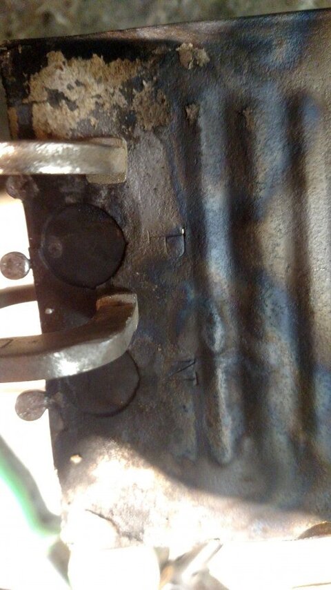
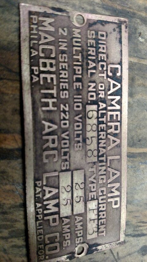
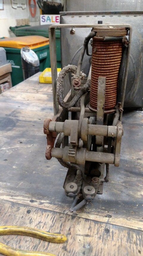
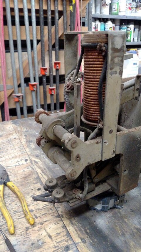
I'm tonight finally opening up the arc sustain mechanism cover to the 25Amp AC/DC Macbeth Arc wash light c.1910 at most for date... (Brass name plate it is also helps determine age.) Other lights in research with different model numbers and slightly different parts shown in photos to them area clearly later - especially given their 30 amp listing.

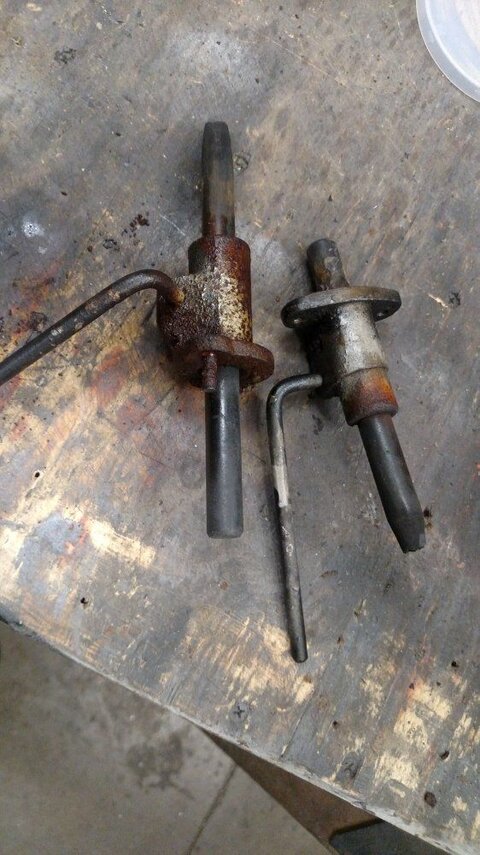
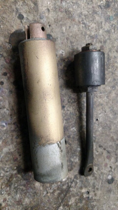
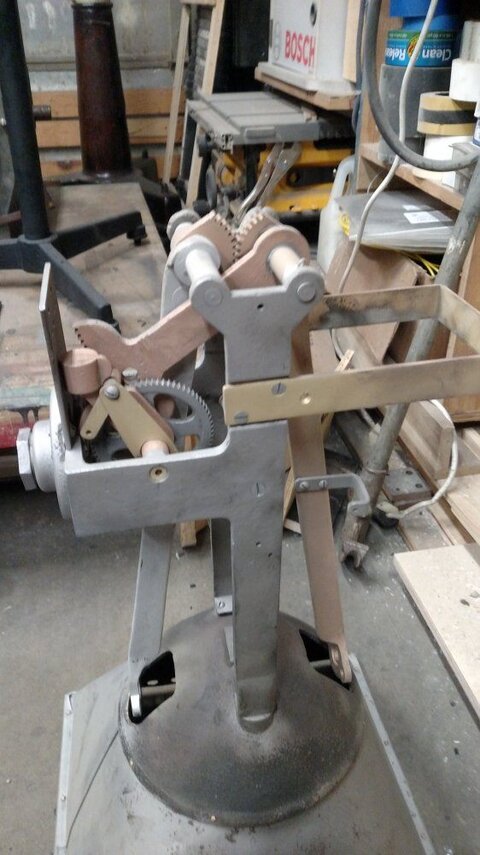
Looking at what is a self sustaining carbon arch mechanism on it. Looking at it, scratching head, looking further.. a... possibly variable resistance to current flow concept of electromagnet with a plate at the top of it to shunt or stop the arc when warn out... or an off switch. And I can also see a possibly a hydraulic or pneumatic cylinder that's compromised or in not knowing what it does or is, might work fine for what ever it does also attached to the gears but not wiring. That plus lots of gears and arms doing stuff and only guesses in how it all worked at this point.

The arc gap when the fixture is level is a constant not touching (self balanced) - this even before working on it - pneumatic cylinder or not a role in working or not. The balance of the arc rods is such you can touch them or bounce away. Strange for such a thing and so old. How the sustaining mechanism works???

I have a 1916 pocket sized product catalogue from a different company listing products with self sustaining arc lights.. why such things went out of existence I have no idea, nor how it works. I have other carbon arch fixtures in stock and there is knobs and levers to control / sustain the beam - this has none. It is clearly a self sustaining carbon arc.

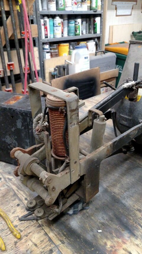
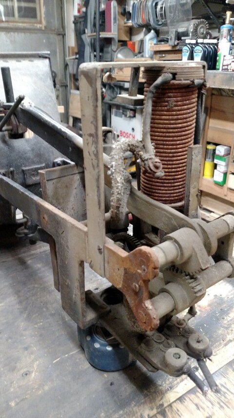
Before I take apart to restore & perhaps make work, I need to know how it/why it works. At least at this point I have a general understanding on how the resistance coils work. - How the counter balance to the arc concept works.... no idea yet.
 

Attachments

  • IMG_20180921_212619054.jpg
    IMG_20180921_212619054.jpg
    109.4 KB · Views: 392
  • IMG_20180921_221517245.jpg
    IMG_20180921_221517245.jpg
    110 KB · Views: 367
  • IMG_20180921_205206812.jpg
    IMG_20180921_205206812.jpg
    107.7 KB · Views: 361
  • IMG_20180921_205146146.jpg
    IMG_20180921_205146146.jpg
    106.9 KB · Views: 372
  • IMG_20180921_205151886.jpg
    IMG_20180921_205151886.jpg
    113.4 KB · Views: 364
Last edited:
A couple of thoughts. The "tank" might be a simple way to add or subtract weight to calibrate the system by adding or removing fluid. Or, it could be a means to dampen the mechanism. In the world of engineering mathematics, this thing is a "control system with feedback." Such systems tend to have overshoot or lag, (over-react or act too slowly) so there's usually some way to dampen or adjust the feedback loop to get the correct reaction for a given input.

The problem you might have is that the properties of the carbon rods are part of the system. Different rods, different weight per unit length and different burn rate.
 
So, here is how they work: (feeling old right now) There should be a positive balance in the the arc rods should want to touch. Once the arc strikes, current flows and the electromagnet (in series with the arc) pulls them apart. The greater the current flow, the more pull and the gap widens. the lower the current flow, the less pull and the gap closes. The air cylinder is a damper which slows the action of the electromagnet so the rods don't bounce or oscillate. It would be very tricky due to the age of the unit to get those parts operating as smooth as they need be for it to function correctly. If anyone can do it, I'm sure it's you! The current level is set by the balance. The more positive the balance (rods want to close) the higher the arc current. The more neutral the balance, the lower the arc current.
Good luck! This is one of the first types of fixtures I remember seeing in the carbon arc world, and I think it was the mid 1960s.

EDIT: As to why the fell out of use, they were replaced with motor driven rods like on the super trouper. These systems also had a bit of self regulation and a counter-winding in series with the arc slowed the motor as the current went up. (or was suppose to!)
 
Last edited:
thanks all and especially JD! Think I have a general understanding, more re-reading of this... Electro magnet explains the coil - what is the plate at the top of the travel for? Refreshing the air cylinder... sure, I do after all work out of the "Turner Tourch" factory, and was once sent a tourch to fix... (Remember the pictures of "Rosie the Riviter", the kerocine tourch she was holding was made in the building I work out of.) Looked at it, but sorry I have no experience with such gas fittings, but we sent him some tour shirts and his torch back.

Now that I know what I'm dealing with, I'll get one more conformation from the brain trust at work and am now able to work on the assembly with thir help. Sounds like the air cylinder will be the hardest part to restore but might be possible.

So in answering my own question, that top plate on the electro magnet is there for once the carbons are useless in length and to shut it off. Wow! that's a lot of science and glad you are not feeling old, but old enough to know and further another generation of knowledge. That's amazing technology for well over a hundred years ago.
 
Interesting in taking apart the carbon arc mounting mechanism tonight, ceramic spacer and mica washers to isolate at least the carbon rod mounts from the arms... but seemingly the levers to release the carbons are "live" as with the rest of the exposed assembly. Definitely a place to stay clear of when live which would not be anywhere near safe to use these days. Also, a thing of say keeping a gap with the levers from near the reflector. Interesting the lower rod mount lever assuming a right hand twist to the threads cannot really travel far to tighten before it hits reflector. This assuming a it's not left twist - both are levers seized. Welding dpt. at the moment isn't busy and will help.

Still a lot more to do. Electromagnet bolts seized, though I did get the stop off... Seemingly, while it will need work, the air cylinder still functions.

That all said and lots of seized bolts... I think this thing will work! Photo shows the exposed live parts of the carbon arc mechanism. That's a lot of yes' Hot parts of the mechanism exposed. Neutral wire feeds from the bottom and goes directly to the electrode. At least I think this... or is the electromagnet fed in return (neutral?) Didn't note which wire on the non-nema open plug went where when cut - but could be important.
 

Attachments

  • IMG_20180924_205047153.jpg
    IMG_20180924_205047153.jpg
    102.9 KB · Views: 259
So the Iriquois Fire 1903 was caused by the sputtering spark from a carbon arc wash light somewhat similar to this wash in concept but not operation, onto a drape. Wasn't the same shape or self sustaining in arc fixture, but otherwise concept the same in open wash light. On this fixture, it's a photo or movie studio light where if the carbon went out - buy quality carbon arc rods.... we just loose a scene and or it self douses. Drapes not near such a thing.

Yet to get out to the Chicago Historical Society that has the fixture attributed with the spark hung next to a PC carbon I have in stock very similar. Want to compare searial numbers of the other PC fixture hung next to it to one in stock in CHS not getting back with serial number.

Believe it was stage right in a position I would assume above the stage manager's table upon the lower power feed in balcony rail - much similar to the Athanaeum in Chicago's position and rail c.1911 should one want to see similar. Read 3 books on the subject & own two. Low quality carbon arcs found common during the day at times had in-pure materials in them which caused sparks. Attendant on the non-self sustaining carbon arc mechanisms he was to be adjusting and or putting out fires from, seemingly he went out on a non-break smoking break during the show and his un-supervised carbon arc sparked in catching scenery on fire wich killed lots of women and children - the start of NBC theater building codes.... locked / chained doors etc., Fire curtains and smoke doors. Really an interesting story to read about. Don't remember if he went to jail.

Assuming a studio fixture, in this case... chance these carbons are "Quality"? From the photo/Studio industry, I don't see in the lower part of the reflector any real landing zones from impure carbons sputtering to confirm this was a systemic problem with the carbon arc spot source from quality rods. Would assume this fixture if not operator maintained given it was self sustaining, was/is the case of only buying the quality rods. (Photo of reflector later - internet slow.)
 
This is AC, so it doesn't matter whether the electromagnet coil is in series with the hot or the neutral. I doubt they made any distinction when this thing was built.
 
Yes, thanks but remember the restored name plate.. AC/DC. At this point, I'll wire the coil thru the hot. I hope this project is educational and as fun for you and I in learning stuff.

Reflector photo just got downloaded.
 

Attachments

  • IMG_20180924_213234455.jpg
    IMG_20180924_213234455.jpg
    65.6 KB · Views: 259
Last edited:
Bad news today. The Fab Sop welder chief boke one of the 1/2" carbon arc's in trying to release it's seized reliece lever. Cannot say I will have done any better in trusting his experience what "liquid wrench" should have done. I trust his experience in heat verses what was done. He did provide me with a website with replacement carbons. Still trust him in braizing back together cast iron casters, and in doing better than I think I could with un-seizing the carbons, and indeed he got the stuck screws on the electromagnet removed.... progress and much the rest cotter pins and buying new 1/2" carbons. High temp wire donated by one of my suppliers on the project... going good.
 
Ship, An AC arc's carbons will burn at the same rate, are usually the same diameter, and will have similar-appearing ends after they've burned for a while. A DC arc will burn its positive much faster than its negative (the trim may have a 20"x3/4" positive and 12"x1/2" negative), the positive will form a definite crater (round, if the carbon rotates) while the negative will form a sort of rounded pencil-point. Most of the light will come from the positive crater, which will usually be pointed at the reflector (in a projection lamp or follow spot.) Old AC/DC arcs will usually have same-size carbons either horizontal in front of a reflector or on a vertical diagonal in front of the reflector.

I got a chuckle out of the nameplate--"i on 110V, 2 in series on 220V". Some years ago I worked on a picture in a steel mill. We got our power from the overhead crane rails which were 250VDC. (Couple feeders with ends "C"-clamped to the rails.) All the arcs (brutes & 150s) were wired in pairs from spider blocks. Two stagehands on each pair--both strike together and opening as simultaneously as they could. Inkies were in pairs, too, but that's another story.
 
Your lamp looks a LOT older than anything I've dealt with tho. Can you make out any date information for the unit? Did/does it have any form of reflector behind the arc? Can you tell what size carbons it uses/used? I'd love to see it in operation when you get it restored.
 
You and me indeed at this point, and I still stand by 1890's - 1910 for date... though given serial number probably in the latter of that early concept. I hope after all the build up it don't just spark, flame up or explode. c.1950 Kliegl 3Kw Dyna Beam... Spent a week + working on it, when turned on it was a great thing.

Replacing mica insulators and garrot standoffs & adding insulation of modern materials where I don't feel comfortable at electrically isolated junctions. Sand blasting for the most part all, if not Tarnex (not impressed in overnight dipping), it removes/clens material, but what is dipped still needs work & further cleaning the bright work.

A question for me comes up. What was the silvered paint used on the reflector? I note also a silvered paint inside the arm crank assembly in tapering from the basic black of the fixture. What is the dirty from arc burning silvered crackling and in places rusting silver paint to the reflector of say a c.1900 light fixture? Something special in a silver paint??? I'll consult my boolks, but a question.

Good news, the phneumtimic cylinder and solenoid/electromagnet were both safely removoved , and with some cleaning should be fine. The phneumatic ciylinder in fact works perfectly fine. Not rubber washers - something different perhaps because of the heat. Has a crack along it's length and something line a dull iron in shine but not the weight of iron. Reminds me of a magnet, though not magnetic. I'll fill the crack so as to help function.
 

Attachments

  • IMG_20180927_001323959.jpg
    IMG_20180927_001323959.jpg
    91.2 KB · Views: 221
Good news, the phneumtimic cylinder and solenoid/electromagnet were both safely removoved , and with some cleaning should be fine. The phneumatic ciylinder in fact works perfectly fine. Not rubber washers - something different perhaps because of the heat. Has a crack along it's length and something line a dull iron in shine but not the weight of iron. Reminds me of a magnet, though not magnetic. I'll fill the crack so as to help function.
Could very well be leather. Materials were a bit limited back then. Old bicycle pumps often used leather. Piston looks weighted, which would make sense. As for the silver paint, probably was silver based! Unfortunately, silver oxidizes and falls off, so it may just be the paint base that is left. I often see pictures of old equipment and the reflectors are black. My understanding is they were not black when they were built! Most restorers miss the whole silver paint bit because there is not a bit of it left to clue them in.
 
Ship, I'd vote for leather piston washers, too. Worked pretty well if kept oiled. As to the reflector, it may have originally been polished and then painted with some metallic paint after it dulled. Have you tried to remove a tiny spot of paint somewhere to see what's below? And if so, what did you find?
 
Ship, I'd vote for leather piston washers, too. Worked pretty well if kept oiled. As to the reflector, it may have originally been polished and then painted with some metallic paint after it dulled. Have you tried to remove a tiny spot of paint somewhere to see what's below? And if so, what did you find?

Metalic. Goofoff has no effect, magnet has no effect. There is what is a crack sized breather groove in it, did a scratch test in it, soft like lead. Suspect lead.

Spent a lot of time sand blasting it today, paint was too far gone. Came up with one half cast bronze, the other half cast iron in gears and frame. Curious one arm was bronze, the other iron. ?Something about current resistance given the stop to the solenoid is on the bronze side.. some form of grounding out concept before frame short - granted non-grounded fixture?

Employee at work further explained the solenoid and will be in as with head of Moving lights inspecting and verifying when this thing is ready. Once I get the thing back together, I have a good amount of oversite. Silver, thanks in how/why, seems like painted on as with the black with a brush. Don't feel as bad about having to remove original paint given the goal of re-producing it and it working again. Photo waiting to catch up.
 
Ship, I'd be very surprised if the piston washers/seals were lead. Not resilient enough to maintain a seal of any kind. I'm still betting on leather (soaked in 100(?) years' worth of oil/grease/??)
 
I would bet leather as well, but it could be doped with something to make a better seal. Could even be a metallic powder / oil mixture. Or, it could have accumulated a coating from rubbing in the cylinder. Things were not too exotic back then, but age may have changed their composition to something that is hard to recognize.
 
No not leather. As pointed out by a co-worker, not heavy enough for lead - but a similar color and soft material unknown.

Did make a breakthrough today in sand blasting the cover to the arm mechanism. Hot/neutral are marked on the cover, and makes sense somewhat in answering questions about the also bronze stop plate on the solenoid (attached to the bronze arm) and why arms are both bronze and cast iron. Hot runs direct to the electrode. Neutral runs to the electrode but also thru the solenoid coil. Seemingly the solenoid coil adjusts arc distance as told above... In starting from shorted, it separates the rods and maintains seemingly a balance between arc and coil auto dimming or moving the solenoid arm dependant on resistance to current flow of the carbons. The pneumatic cylinder slows down the operation so it's not a jumpy movement in sustaining the arc. The solenoid has a fork shape to it due to balance needs - center inside the solenoid, one arm contacts an adjustable stop plate attached to the bronze arm. In theory, this plate is to auto kill the fixture if the rod gets too short. At least that's the theory before re-assembly.

Initial thought before re-assembly and understanding the workings further, this plate shunts the solenoid and opens the gap so as to kill off the arc. Were this the case, explains at least why the arm is bronze, but not why much of the mechanism is also in mixing and attaching to cast iron - unless cheaper that way for some parts. Also if the case of being a shunt, would explain why it's not grounded given a frame short.

Sub-theory, could this un-identified stopper for the brass cylinder pneumatic be... I don't know, also some form of magnetic when current flows to it? If such an unknown material once electrically charged shorts also the pneumatic cylinder piston opens?.... Possibly the purpose? That would be a hard concept given from memory at least the pneumatic cylinder is attached to both the bronze and cast iron parts of the mechanism. And the cast iron part is not electrically connected to anything but the studio floor. Probably not the case, but a thought.

As for the bad looking post sand blasted cover to the mechanism... the bottom rear of the cover - once badly repaired by like brass brazing (old repair perhaps after the light was dropped), had failed again. I was attempting to solder a plate to the rear which only half worked... should have had our welder do it. In the end, was half stuck the plate, and 3M DP-605 epoxied the rest of it to my new plate. The added plate is necessary for not just integrity of the repaired cord attachment screw to fitting holes, but also for the strength of the cover. Had to remove the paint, had to repair the terminal holes. Only real modification to the fixture at this point other than having to have our welder repair the cast iron swivel casters on 2/3 of the casters. Tough challenge for him in somehow attaching back together +100 year old cast iron.

Unfortunate, tonight I checked reproduction Sears Catalogues from 1897 and 1902. The fixture was in neither.
 

Attachments

  • IMG_20180927_001323959.jpg
    IMG_20180927_001323959.jpg
    91.2 KB · Views: 238
  • IMG_20180928_200316558.jpg
    IMG_20180928_200316558.jpg
    84.3 KB · Views: 254
Final finishing of the arm mechanism and fixture. The inside of the arm mechanism was all painted the same silver as the reflector. Seemingly once assembled & wired, the outside was all thick coated black painted. Believe in some areas of photos under the silver having been sand blasted might have been either primer of vehicle in also seeming black but not intended that way.
So in explaining how this thing works, obviously it would be better to re-spray the outer shell high temp. black and use dulling spray and lacquer to match original paint. But the inner mechanism was painted silver.

Electrically any possibility that a thick layer of paint say is there to stop a short to frame from the winding coils of the solenoid or for other reasons? Why was the mechanism painted silver? Cover plates were black. Paint was after wiring given electrical wiring bolts and terminals were also painted. Paint was electrical insulation after wiring?
 

Attachments

  • IMG_20180928_212136592.jpg
    IMG_20180928_212136592.jpg
    88.5 KB · Views: 220

Users who are viewing this thread

Back