Conventional Fixtures "Vegas Strips": "Broken" Mini-Strip sections

rochem

Well-Known Member
Mods: Feel free to change the title of this thread if you can think of something more decriptive/accurate.

So I feel kinda weird asking this question, but can anyone explain to me in detail how "Vegas Strips" work? I'm talking about the MR-16 Mini-Strips available from L&E that come in sections - specifically, their product no. 6560-3. As I understand it, it's basically a 6' Mini-Strip that's been broken into three pieces to make it easier to fit in small places or around curves. The only time I've ever seen these in person or heard about them was at In The Heights on broadway, where they used 8 of these for footlights, then had to completely cover the 9th one in blackwrap in the pit since it had to be connected as well.

Has anyone ever used these before? While I understand the basic concept, I don't really understand how they actually work together. Are the three sections permanently wired together, or is there some sort of connector that you connect them with? Can you run the remaining sections off to a remote location, or do they have to be right next to eachother? What would happen if you tried to only use one or two? I've spent a long time searching around the interwebs, but nothing's really been very helpful - and the search results for "Vegas Strips" haven't been particularly helpful either... :rolleyes:

Thanks!
 
Last edited by a moderator:
re: "Vegas Strips"; "Broken" MiniStrip sections

The basics behind low voltage MR16 strips is to have 10 - 12 volt lamps, typically a 50 or 75 watt spot of flood lamp, wired in series, in one circuit. You provide a 120 volt power source for power and dimming control (if off a dimmer) and as result of the series wiring, all 10 lamps in the circuit "absorbs" the 120 volt power (maybe somebody else can explain that part better).

I see these "broken strips" on the L&E site but have never actually seen them in use. The concept is the same as a standard 30 or 40 lamp single unit and in operation with either the broken 6ft or 8ft versions, you must keep their wiring continuous for a 10 lamp circuit, even if it's in 3 sections, else the 12 volt lamps will go Jimi on you in short order. Obviously (and as stated in the spec's), the broken versions don't have feed thru cabling, but instead have interconnect cables to complete the 10 lamp circuit.

One issue is that you don't get an even distribution of the colors as the L strip will have 4 lamps for circuit A, 4 lamps for circuit B and 2 lamps for circuit C, due to the design of mounting 2 lamps side-by-side in a circuit. The center strip will then have 4 lamps for circuit A, 2 for circuit B, and 4 for circuit C, etc....
 
Last edited:
re: "Vegas Strips"; "Broken" MiniStrip sections

I think you described that rather well Steve.
Now if someone in the crowd could post a photo or two of these critters in use, we would be onto something here...
 
re: "Vegas Strips": "Broken" Mini-Strip sections

I have seen these exactly once, twenty years ago. Surprisingly, in Las Vegas. I'll make a phone call later today to see if they are still there, but I kind of doubt it. The lighting in that room has been redone at least four times since then. rochem, where did you get that they are called "Vegas Strips"?

3x2P&GM=[AABBCCAABB]=3xL5-15F . 3xL5-15M=[CCAABBCCAA]=3xL5-15F . 3xL5-15M=[BBCCAABBCC]

The interconnects may not have been L5-15, or may have been 3 different styles of 15A twist connectors--I can't remember. Obviously, extreme care must be taken to ensure everything is plugged correctly before powering up.

1. Are the three sections permanently wired together, or is there some sort of connector that you connect them with?
2. Can you run the remaining sections off to a remote location, or do they have to be right next to each other?
3. What would happen if you tried to only use one or two?
1. As said above, I think it was L5-15 between sections.
2. Given the proper cable/connectors, you could separate them more than the 1.5' whips allow. Since it's only 12V, might have some issue with voltage drop over a very long cable.
3. Nothing, they simply wouldn't light up, as the series circuit(s) would not be complete.

...Obviously (and as stated in the spec's), the broken versions don't have feed thru cabling, but instead have interconnect cables to complete the 10 lamp circuit...
I thought mine did have 2P&GF "outs" on the last unit, but I guess not. I don't see why it couldn't. ... Oh wait, yes I do. It would take two additional wires in each of the interconnectors to "pass thru" the 120V to subsequent "full" strips (essentially, creating a combination wiring, series / wiring, parallel circuit).
 
Last edited:
re: "Vegas Strips": "Broken" Mini-Strip sections

What Derek describes might be configured as shown:
Yup, that's it! Except:
1. No female 2P&G connectors.
2. I've always lived by the rule that ckt#1 was the first one on the male end. Any particular reason you chose to go CBA instead of ABC?
3. If we use the premise that one goes by the order of the knock-outs when interconnecting striplights (regardless of what the plugs are labeled), your plugging between SL and SLC strips is wrong.
 
Last edited:
re: "Vegas Strips": "Broken" Mini-Strip sections

Yup, that's it! Except:
1. No female 2P&G connectors.
2. I've always lived by the rule that ckt#1 was the first one on the male end. Any particular reason you chose to go CBA instead of ABC?

No I just got tired of trying to draft the fixture exactly as built and opted to show how it essentially functions instead. In reality all cables are on the fixture ends as 3 different strain reliefs clustered in a group. No point in drafting that.

In theory, you can have pass thru females as the loading per color circuit for the 3 strips is only 750 watts if using 75 watt lamps, thus you could power add'l strips off a 20amp circuit, IF L&E built it that way. Since one of the strips HAS to have a set of Male plugs to provide power, it always ends up as either the L or R strip, but never center. If what you describe is how they build them, with a different connector for series connections (logical), then you will always have defined L, C & R strips, thus no reason to not build with pass thru, even thought the spec sheet say's they don't normally.

Somebody needs to take a picture.
 
re: "Vegas Strips": "Broken" Mini-Strip sections

... thus no reason to not build with pass thru, even thought the spec sheet say's they don't normally.

Somebody needs to take a picture.
Except, as I said in my epiphany above, pass-thru's would require 3x 5-conductor (1xG, 2x12V, 2x120V) connectors for the interconnects.

If the fixtures still exist, I'll try to get a picture.

EDIT: Just got word that the fixtures are long gone, and in fact the Master Electrician there now had no idea what I was talking about. :(
 
Last edited:
re: "Vegas Strips": "Broken" Mini-Strip sections

Except, as I said in my epiphany above, pass-thru's would require 3x 5-conductor (1xG, 2x12V, 2x120V) connectors for the interconnects.

If the fixtures still exist, I'll try to get a picture.

Correct me if I'm dain bread, but you could in theory, use the pass-thru wiring as L&E provides for a single circuit 30 lamp strip and simply wire ea. cable in the circuit to pickup the last lamp in the series in the L strip, to feed that hot to the first lamp center strip. Thus the Hot is the continuation of the series wiring, the neutral carries to the next strip (as it's required at the end of the circuit) as well as providing ground, repeating for 2 more circuits. Could you do it with a multi-connector ? - Sure, but it's seems easier for L&E to make it this way as the cables and strain reliefs are already built for non-broken strips.

But it's all theory and speculation at my end as I've never seen these things in person.
 
re: "Vegas Strips": "Broken" Mini-Strip sections

I think we're both saying the same thing Steve, but perhaps in different ways.

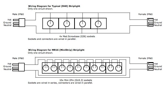
An illustration comparing a normal striplight with an MR16 version:
striplight wiring.jpg
If the MR16 unit was separated ("broken") between any two pairs of lamps, one would have five conductors to deal with, if one wanted retain pass-thru capability.
 
Last edited:
re: "Vegas Strips": "Broken" Mini-Strip sections

The basics behind low voltage MR16 strips is to have 10 - 12 volt lamps, typically a 50 or 75 watt spot of flood lamp, wired in series, in one circuit. You provide a 120 volt power source for power and dimming control (if off a dimmer) and as result of the series wiring, all 10 lamps in the circuit "absorbs" the 120 volt power (maybe somebody else can explain that part better)

No, that actually makes perfect sense. I knew Mini-Strips were wired in series, but I never actually understood why they designed the fixtures that way. It's really just basic electrical theory - the equivalent resistance of several resistors wired in series is equal to the sum of the individual resistors, and all that jazz.


rochem, where did you get that they are called "Vegas Strips"?

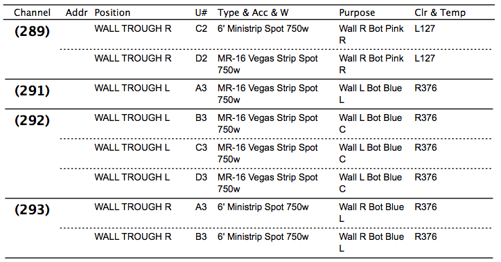
It says so on the plot,

Screen shot 2011-05-18 at 3.38.59 PM.png

and on the paperwork.

Screen shot 2011-05-18 at 3.41.10 PM.png

Although, I'm almost certain I've heard the term before - I think that's what they called them at Heights as well. Might be a New York thing - something weird, rarely seen, and difficult to understand? Put Vegas in the name! :p

Now if someone in the crowd could post a photo or two of these critters in use, we would be onto something here...

Agreed!
 
re: "Vegas Strips": "Broken" Mini-Strip sections

I'd love to see the connecting connectors !, as one thing that occurred to me is if you are using 3 separate connectors, you really, really HAVE to make sure you plug A to A, B to B and C to C, as there's the potential to have too few lamps in a series if you screw it up.
 
re: "Vegas Strips": "Broken" Mini-Strip sections

I'm thinking it may have been an L5-15, L6-15, and L7-15, so no possibility of connecting them wrong. But I really can't remember. I do recall that they were small, round, and white. And I'm pretty sure had red, white, and blue (or maybe it was red, blu and grn) e-tape on them.
 
re: "Vegas Strips": "Broken" Mini-Strip sections

Well, I sent an email to L&E yesterday requesting some information about the strips, and I got a call back from someone there today who answered a number of my questions. Here are the highlights:

Yes, "Vegas Strip" is a fairly standard industry term for the strips. It apparently originated from the way in which they're wired (take that as you will).

Each section uses L5-15 twist-lock connectors on the interconnect cables. All three circuits are the same connector, but each connector is clearly labeled with 1/2/3 and/or red/blue/yellow.

The last (third) section of each strip does NOT have 120V 2P&G pass-through connectors like normal mini-strips do, likely for the reason Derek specified.

She highly recommended that I should NOT, under ANY circumstance, cover unused fixtures in blackwrap. Yeah...

And, finally, she suggested that a long run of interconnect cable between sections shouldn't be a problem. I mentioned the potential for voltage drop and threw out the figure of 75', and she said it shouldn't be a problem. I'm not 100% sure that I believe her, but it's at least something to go on.

And no, they have no photos of the strips at all. Go figure.
 

Users who are viewing this thread

Back