You are using an out of date browser. It may not display this or other websites correctly.
You should upgrade or use an alternative browser.
You should upgrade or use an alternative browser.
California plug?
- Thread starterderekleffew
- Start date
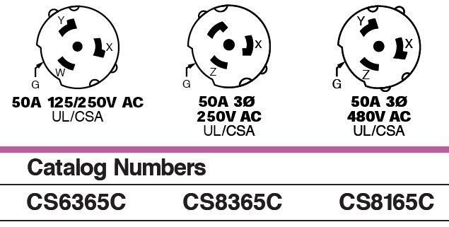
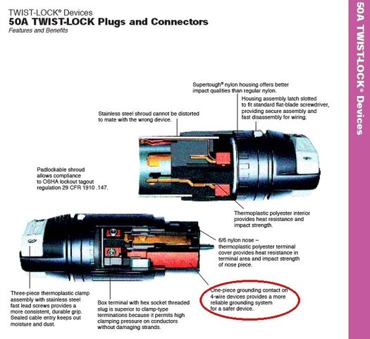
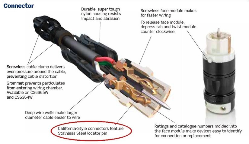
They tell everything except WHY it's called a California plug!Those diagrams and product [-]broschers[/-] brochures tell a lot.
Last edited:
I knew I was spelling it wrong, autocorrect said it was a word so I went with it.
I certainly couldn't tell you why they named it that, but from everything I've read it's just designed to be an ultra durabe, lockout device compliant connector, I'm sure the lockout feature is what it has to do with CA, but the locator pin also makes the differnciation.
I still maintain it is a usefull tool to prod non workers.
porkchop
Well-Known Member
The spike is definitely the ground. I am not sure if there is some sort of mechanism to disconnect the power if the ground isn't in contact; I had never heard of this but it seems believable.
Well my previously deleted post is back so I guess I can actually post this time. There's a great mechanism in the three phase connector, it's called the ground spike is the only return leg, if it's not connected there is no circuit. In single phase you're depending on how it's wired.
As far as why the spike is on the female connector, I would guess it's for the same reason that touring shows turn around ground and neutral in feeder. On the ground leg power is actually flowing from the load back towards the power source so the end that sticks out out of the conductor should be on the return side not the load side.
I happend upon one today, wired up with a 4 conductor cable. Green, Black, Red, White, I imagine it was a 220V/110V single phase setup. (3P4W) the female connector had it's prominent locator pin. The thing is the connector had a fair bit of mud caked on it. Couldn't tell you how it was muddy and up on the second floor lighting cove.
Can you please explain the theory behind that?
Are you sure about that?
Consider the purpose of a grounding conductor and alternating current flow...
epimetheus
Well-Known Member
Based on what I've seen of this connector system, it's only rated for 120/240V single phase and 208V, 240V, 480V three phase. Note that the three phase configurations do not allow phase to neutral loads, only phase to phase. The single phase configuration gives 2 hots, a neutral, and a ground. The three phase configurations give you 3 hots and a ground. In these cases, the ground conductor is the equipment grounding conductor, and as such is a non-current-carrying conductor. It DOES NOT carry the return load current, that would be the neutral. This is why the three phase configurations do not support phase the neutral loads.
bishopthomas
Well-Known Member
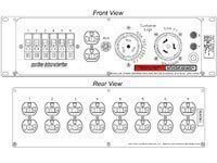
We use California connectors (CS6360c and CS6361c) all the time for small single phase distros. These are often called "rack pack" distros because they are seen quite often in amp racks. There will be outputs from the main distro feeding the rack packs for two legs of 50A service. It also makes tying in to a panel easy - just pop in a double 50 breaker to power the rack pack distro.
... These are often called "rack pack" distros because they are seen quite often in amp racks. ...

Motion Labs - 3 Space Rac Pac
Anvilx
Active Member
Well my previously deleted post is back so I guess I can actually post this time. There's a great mechanism in the three phase connector, it's called the ground spike is the only return leg, if it's not connected there is no circuit. In single phase you're depending on how it's wired.
As far as why the spike is on the female connector, I would guess it's for the same reason that touring shows turn around ground and neutral in feeder. On the ground leg power is actually flowing from the load back towards the power source so the end that sticks out out of the conductor should be on the return side not the load side.
Power isn't flowing persay because if part of the circuit is energized than the whole circuit is energized. While flipping the genders around to prevent accidental contact is a good idea, lets think about the situation. The reason that this ground exists is so that if something shorts and energizes a piece of metal equipment you won't get shocked because there is a path of less resistance to the ground. However this means that all metal panels are connected to ground. So then whats the difference between touching a power distro and touching the end of the connector?
If the ground contact of a California plug had potential relative to ground it would be a more serious shock hazard them most conectors. Most California connectors have a Stainless cover around the male contacts that is tied in with the ground, if that had potential you would get shocked trying to move or disconnect the plug. I hope no one EVER switches wiring around from what it should be according to spec.
I believe the California plug gets its name from being developed as a safer connector for the early days of the Hollywood Film Studios. The first hi-ampereage connectors used in the studios were paddle plugs used in theatres, which were ungrounded. The California plug was grounded by the outer steel shroud, which also protected the male contact pins from damage when the cables are dragged around the set every day. The grounded shroud helps absorb the Arc-Flash if the connector is plugged or unplugged while energized. The paddle plug was notoriously dangerous for Arc-Flashes, especially in the older DC powered Theatres in the first years of electric lighting for the stage! The locator pin on the female connector is only to help guide the male and female parts together because the steel shroud makes it hard to see the contacts during connection, this is also why the shroud is keyed.
Power isn't flowing persay because if part of the circuit is energized than the whole circuit is energized. While flipping the genders around to prevent accidental contact is a good idea, lets think about the situation. The reason that this ground exists is so that if something shorts and energizes a piece of metal equipment you won't get shocked because there is a path of less resistance to the ground. However this means that all metal panels are connected to ground. So then whats the difference between touching a power distro and touching the end of the connector?
Grounding is quite possibly THE single most misunderstood concept of electrical wiring. The green wire, or equipment grounding conductor is not there to bring the current back to the earth. Pounding a grounding stake into the dirt will not keep you from getting shocked. The purpose of that green wire is to provide an Effective Ground-Fault Current Path.
NEC 2011
Article 250.2 Definitions
Effective Ground-Fault Current Path
An intentionally constructed, low-impedance electrically conductive path designed and intended to carry current under ground-fault conditions from the point of a ground fault on a wiring system to the electrical supply source and that facilitates the operation of the overcurrent protective device or ground-fault detectors on high-impedance grounded systems.
In short that green wire is there so that when a short circuit occurs, the OCPD, whether a breaker, a fuse or a ground fault circuit interrupter will activate, de-energizing the circuit. De-energizing the circuit is what will save your life in the event of a short circuit.
Last edited:
techieman33
Well-Known Member
We weren't hanging that many motors but going in advance of the main show loadin. I was building a theatre in an arena for a Broadway package. I supply all the motors, truss and curtains to simulate a theatre. The hardest part is building a traveler from scratch each time. I have it down to building a 50ft opening in 30 minutes.
Similar threads
- Replies
- 2
- Views
- 811
- Replies
- 0
- Views
- 324
- Replies
- 6
- Views
- 4K
Users who are viewing this thread
Total: 1 (members: 0, guests: 1)


