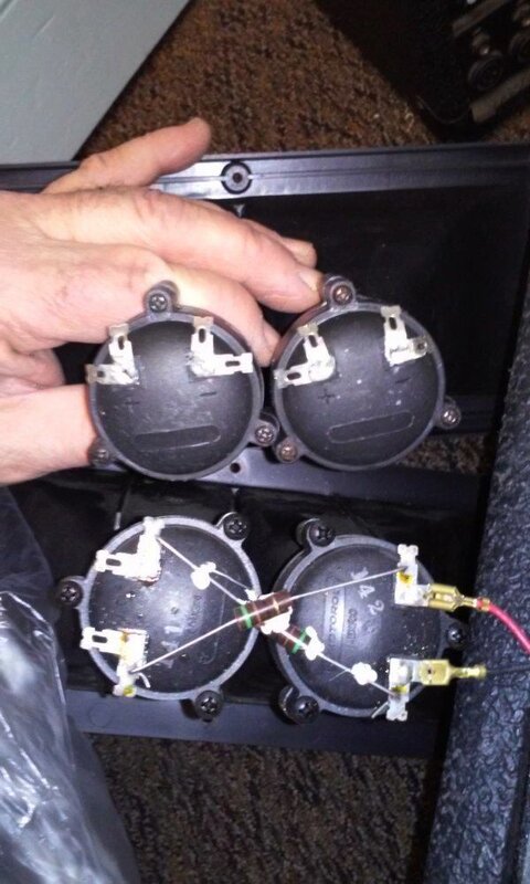
Interesting! The wiring in the picture is actually wrong. Was that straight from the factory?
What you have is a couple of piezoelectric drivers. These are used for high frequency and have the advantage of having a natural
crossover property. At low frequencies, the
impedance goes way-high so they effectively don't conduct. They don't have a
voice coil, just a crystal attached to a
diaphragm. They don't like voltages above about 25 volts, so there are some limiting resistors in the
circuit. If I can see the picture clearly, it looks like the resistors are green-brown-black. That translates to 51 ohms. Usually, the piezo
tweeter is in series with the
resistor. The
layout in the picture shows the drivers to be mounted opposite to each other. That would mean one
resistor is wired between + on one
unit and + on the other
unit. The other would go between - and - and that's why they cross the way they do. The problem I see is that the red
wire should go to the + on one
unit and the black should go to the - on the other one. That way each would have a
resistor in series with it.
What the picture shows is the red and black going to one
unit, and the resistors bridging over to the second. This would be wrong as the
tweeter with both wires would get full
power and the other
driver would have both resistors in series with it.
The resistors look good. They are 51 ohms, standard carbon, 1
watt, 5% tolerance (gold band = 5%)
EDIT: A little info on the concept- Piezoelectric tweeters operate at a fraction of a
watt but are incredibly efficient. If you try to
meter them, they will look bad as they will read as almost an open
circuit. When you go to
meter them you will hear a faint click. This is normal. At high frequencies they
drop to about 100 ohms. At very high frequencies they
drop even lower and the
resistor protects them.
Here's a real detailed article about their use:
http://www.pulsardevelopments.com/products/detail/piezoan.html