Clear-Com Radio Interference

ihalevi

Member
Hello.

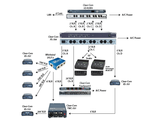
Attached is a sketch of our Clear-Com system at Harvard Stadium.

Without the TWC-701, we've used this system for a few years, and it's been great. We just added the TWC-701, and now we suddenly have RF Radio interference in the Ch. A headsets (we can hear a nearby radio station). When I remove the TWC-701, the noise is gone. If I remove the Whirlwind SPLIT 6 (but keep the TWC-701) the noise is also gone. The noise is only there when both the TWC-701 and the Split 6 are connected. Any ideas how to get rid of the noise?


Thanks.


Imry
 

Attachments

  • Harvard Stadium Clear-Com Flowchart.png
    Harvard Stadium Clear-Com Flowchart.png
    53.5 KB · Views: 571
I would check the cable that is used to attach the TWC-701 look for a cold solder joint. i have had a radio station coming so loud that could not hear anything else and it was a bad solder.
 
Check solder joints as @coldnorth57 said and verify all of your cables are passing signal on all 3 pins and that shields/drains are only connected to pin 1, not to the connector shells. Usually noise and interference in a comms system is a wiring/grounding issue and solving it requires methodical verification of the cabling and connections in use.

Try and leave the electronics in place but swap cables 1 at a time. Try disconnecting the RS-701's from the Split6 and connect them locally with 5' cables instead. Try connecting the RS-703 locally at the RS-703 with a short cable. If eliminating the hundred-foot cable runs makes your problem go away, you know you have a cabling issue and can start reconnecting those longer length cables 1 at a time until the problem shows back up.

Are the XLR's all indicated actually portable cables or are some of those links using cabling installed in conduit/walls?
 
Based on your description, I think the A input of the TWX-701 is demodulating the RF. The long runs connected to the Split 6 are acting as antennas. See if it quiets when you disconnect the long runs from the Split 6, one at a time. Then try disconnecting all of them but leaving the Split 6 in line. It would also help to know if the station is AM or FM. The station should give an ID within +/- 5 minutes of the top of the hour.
 
Thanks for the responses.

All the XLR cables have solid connectors on the ends. I cannot open them.
But I can tell you this - if I take all the cable runs out of the system, and just have the PS-704 connected to the Split 6 and the TWC-701, I still get interference. It's something about those two devices.
As for which radio station - there are actually two at the same time. Sounds like FM to me.

Call the support folks at Clear-Com.

Clear Com is UNBALANCED with DC signalling, Telex/RTS is BALANCED audio with tone (20k ish) signalling. That Clear Com works in some pretty hostile RF environments defies most of our logic about long, unbalanced lines, but it sounds like something in the TWC701 isn't right.

I solved a Mackie mixer "radio receiver" problem is a church install 20 years ago with ferrite beads (Mackie had a service bulletin about it), and I expect Clear Com has a similar fix if the 701 isn't 'defective.'
 
Thanks for the responses.

All the XLR cables have solid connectors on the ends. I cannot open them.
But I can tell you this - if I take all the cable runs out of the system, and just have the PS-704 connected to the Split 6 and the TWC-701, I still get interference. It's something about those two devices.
As for which radio station - there are actually two at the same time. Sounds like FM to me.

That suggests the Split 6 has a problem, such as a cold solder connection. I would open up the Split 6 and re-flow all of the solder joints. If that does not resolve it, I would look to see whether XLR pin 1 is bonded to the chassis. Whatever it is, change it to the opposite and see what happens.

AM will sound very bright like FM when demodulated in this way. AM radios have poor frequency response due to their IF filter stage, but your Clearcom has no filter. Plus, the AM transmitter applies pre-emphasis, a high frequency boost. The only way to tell is to listen for the station ID.
@ihalevi
Writing in support and full agreement with @FMEng

Up here in Canada, your interfering broadcaster may be legally simulcasting. An amateur group operating six (nearly antique) original 500 series stainless steel belt-packs swore a commercial FM transmitter's antenna part way up an 1100 + foot TV transmission tower five miles away was bleeding into their single channel basic ClearCom's Belden 8760 shielded wiring installed in their dedicated grounded EMT conduit. After much co-operation from ClearCom in the days when they were still based in California and the suggested addition of many ferrite beads, the offending interference proved to be from the same commercial station's 50 Kw AM transmitter site about three miles directly West of the theatre's venue at essentially the same elevation only a few miles away on the same provincial highway. You could practically listen to the AM station with only the approximately four foot cables attached to their Beyer DT108 headsets WITHOUT plugging them into their near antique original potted RS500 (Possibly RS501) beltpacks. The more you know what you're chasing, the better your odds are of winning.
EDIT: Added an inadvertently omitted word.
Best of luck to you.
Toodleoo!
Ron Hebbard
 
Last edited:
It seems like it's the TWC-701 causing the issue. I got the 6-splitter out of the chain, and still I'm getting interference now. Clear-Com Support keeps asking me to try different cables. I did that. No change.
Does anyone know if there's an XLR in-line connector that could filter out RF interference from a Clear-Com signal (just like a high-pass filter, or ground loop isolator)?

Thanks.

There are ferrite cores that the XLR cable can be wrapped around or through to prevent the RF from getting into the Clear-com. In order to get the proper ferrite core, we have to know what frequency band is causing the interference. The reason is the ferrite material is formulated to be effective in certain frequency ranges. Report back whether it's AM or FM and I can recommend what to buy.

Neutrik makes an XLR connector with some RF filtering built in, but it is only effective at cell phone frequencies, so it isn't a solution here.

I believe the frequency is around 93 FM.
 
Do you have a place to put one? Usually that would be on the master base station or power supply? If so, get a cliplead and try that out.

Power supply's chassis provides the ground reference to the cabling. You should not have to supplement this with additional bonding jumpers between cabling infrastructure and conduit ground.
 
Power supply's chassis provides the ground reference to the cabling. You should not have to supplement this with additional bonding jumpers between cabling infrastructure and conduit ground.
@MNicolai @Jay Ashworth @ihalevi I've ALWAYS found ClearCom wired Party Line systems work best, quietest and most cross-talk and interference free by grounding them at one and only one point with that ground being via the master station / central power supply's line voltage power cord. From basic single channel portable or fixed systems, to installations with 12 discrete channels including dual redundant multi-channel central power supplies, operating with single, dual, quad, and 12 channel remote fixed or installed stations, in ALL cases any interconnections between the shields of different channels and / or having any of the field wiring contact ground has ALWAYS led to problems, typically a higher noise floor, often with a discernible increase in cross-talk. All of my Clear Com work has been with basic PL (Party Line) installations prior to any of Clear Com's relatively newer systems with 2 discrete channels on a single shielded pair or any of their digital systems.
Toodleoo!
Ron Hebbard
 
Grounding and shielding isn't that effective at RF frequencies because audio and AC cabling is inductive. The best thing to do is pass the cable through a split core, ferrite toroid. If it's an FM station, the following is a good choice for maximum effectiveness.

http://www.amidoncorp.com/2x44-6451p2/


The range of different shapes and sizes
http://www.amidoncorp.com/43-material-round-cable-clamp-ons/

The toroid should be placed on the cable within a few inches of the XLR connector plugged into the noisy belt pack. The more wraps of the cable through the center of the toroid, the more effective it becomes.

If the 6451p2 is too big and heavy, you can try smaller ones, but less length reduces the filtering. A smaller inner diameter reduces the number of turns of cable you can fit into it. A thinner cable helps increase the number of turns that will fit. A zip tie or electrical tape around the whole thing will keep it snapped shut permanently and a bit more rugged.

If you use a toroid at the belt pack and still have radio, try putting one at the other end of the cable that plugs into the power supply. After that, it's time to put one on the headset cable because RF can get in there, too.
 
um, did I mis-read the diagram, or are there 2 places where a ground loop could develop because there are 2 paths back to the PS-704?
 
um, did I mis-read the diagram, or are there 2 places where a ground loop could develop because there are 2 paths back to the PS-704?

The TWC is intended to receive multiple channels from a PS-x or MS-x without lifting any cable shields along the way.
 

Users who are viewing this thread

Back