Electrical distribution along lighting grid

Hi guys,

I want to distribute 80 amps (4 electric circuits) in various locations, around a 20' x 20' lighting grid, in such a way that it (the electrical wiring, which will be in EMT, or Flex conduit) doesn't interfere with the pipe itself, and the lighting clamps. How would you do it?

(The long version of the question...)

We have 4 circuits that the building GC left for us in junction boxes in the ceiling. I want to bring the circuits down to the lighting grid (approximately 20' x 20'), and distribute those five circuits around the perimeter. I also see myself using a similar method to put DMX outlets at various places along the grid.

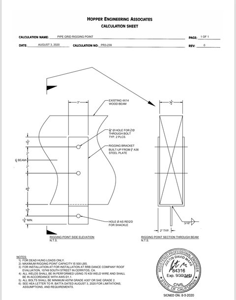
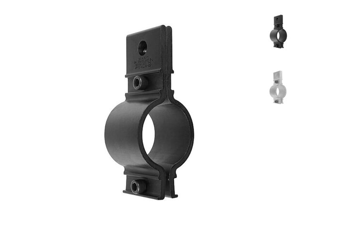
The grid will be about 5 feet below the ceiling, and held by Mega Batten Clamps, which in turn will hanging from 1/8", 7x19 aircraft cable, which is attached to ceiling beams clamps and ceiling beams that a structural engineer has signed off on.

I have a commercial contractor who will do the work, however he hasn't done work in a theater. The last time I had to do something like this, was a few years ago when I outfitted a theater with new LED fixtures. We ran two EMT systems for AC and DMX. and actually attached them to electrics.

In this scenario, I think that electrical should be above the grid (I'm thinking 8-12"), in such a way that it doesn't interfere with how the lighting fixtures clamp on to the pipe.

In a perfect world, I'd sell them something like ETC battens with both electrical and DMX built in, or additional pipe that would allow the EMT to run parallel, but this is a non-rofit that doesn't even know if they will survive COVID. But the project was already underway when it hit.

Thanks!
 
I've seen lots of standard 4x4 electrical gutter/raceway used with SO whips and cable receptacles coming out the bottom at the appropriate spacing. Anywhere from 1' to 10' whips. The raceways are generally 6" to a foot above the grid. DMX distribution could be done with splitters mounted on the grid and cables radiating out (maybe allow a separate AC circuit for the splitters?).
I would definitely use threaded rod to hang the grid from your beam clamps rather than aircraft cable to make the grid more stable. Also bolting or welding flanges on several of the pipe ends and attaching to the side walls to prevent the grid from moving. A rigidly fixed grid will be much more useful and easier to work with than a floating one. If you were working with more circuits, a cable tray system works wonders, albeit probably quite a bit more expensive.
Thanks for the response. This is what the structural engineer has approved for the ceiling rigging, and I’ve found a fabricator who can make it. Combined with the batten clamps for the pipe, aircraft cable seemed like the shortest distance between two lines.

I can cut and swage the cable myself, but to do the threaded rod, I’d need a whole lot of extra components. I’d have to adapt the threaded rod to the hole on the bottom of the clamp, then I’d have to adapt the other side to something that would fit the mega batten clamp.

Additional info that may or may not affect your opinion: Its a black box for kids, and I’ve been told nobody at the facility would ever touch the grid. They’d have us come back for any service/maintenance. Also, essentially all of the fixtures are movers, also for that reason.
 

Attachments

  • 904CF49A-4A2A-4086-B00D-AA0D7A629EFE.jpeg
    904CF49A-4A2A-4086-B00D-AA0D7A629EFE.jpeg
    287 KB · Views: 228
  • F548804D-5CCF-4205-A7E9-8BEB38339F3D.jpeg
    F548804D-5CCF-4205-A7E9-8BEB38339F3D.jpeg
    77.7 KB · Views: 233
You may find that with a 20' x 20' grid and power only around the perimeter you will be running cables around to positions in the middle. Better plan for 10'-15' whips from your perimeter duct or some ducts/outlets within the grid area.

Thanks for the response, I shouldn’t have said “grid”. This is more just a rectangle, that’s closer to 18’ x 22’. Although by design, they later could add 90-degree cross beams to make it more of a grid. But I do like the idea of whips for distance.
 
A thought

if you have movers, you probably want to find some waytostabalizethe grid. IE if the movers move, you really dont want the pipes to move
 
Thanks for the response. This is what the structural engineer has approved for the ceiling rigging, and I’ve found a fabricator who can make it. Combined with the batten clamps for the pipe, aircraft cable seemed like the shortest distance between two lines.

I can cut and swage the cable myself, but to do the threaded rod, I’d need a whole lot of extra components. I’d have to adapt the threaded rod to the hole on the bottom of the clamp, then I’d have to adapt the other side to something that would fit the mega batten clamp.

Additional info that may or may not affect your opinion: Its a black box for kids, and I’ve been told nobody at the facility would ever touch the grid. They’d have us come back for any service/maintenance. Also, essentially all of the fixtures are movers, also for that reason.
Unless you've bought the supplies already, just specify the correct beam clamps and batten clamps for threaded rod. Then all you need is a hacksaw and a bunch of nuts, bolts, washers.
I don't really think I've ever seen a "permanent" grid hung with aircraft cable. One other thought.... although you've been told nobody would ever touch the grid, "ever" is longer than your lifetime and the lifetime of whoever told you that! I've been in lots of places that have evolved considerably from what they were built for initially. Just something to think about.
 
Thanks for the response. This is what the structural engineer has approved for the ceiling rigging, and I’ve found a fabricator who can make it. Combined with the batten clamps for the pipe, aircraft cable seemed like the shortest distance between two lines.

I can cut and swage the cable myself, but to do the threaded rod, I’d need a whole lot of extra components. I’d have to adapt the threaded rod to the hole on the bottom of the clamp, then I’d have to adapt the other side to something that would fit the mega batten clamp.

Additional info that may or may not affect your opinion: Its a black box for kids, and I’ve been told nobody at the facility would ever touch the grid. They’d have us come back for any service/maintenance. Also, essentially all of the fixtures are movers, also for that reason.
With movers, are you concerned with the grid swinging like a pendulum; especially if / when you get your movers moving in synch' with music and choreography?
Toodleoo!
Ron Hebbard
 
Unless you've bought the supplies already, just specify the correct beam clamps and batten clamps for threaded rod. Then all you need is a hacksaw and a bunch of nuts, bolts, washers.
I don't really think I've ever seen a "permanent" grid hung with aircraft cable. One other thought.... although you've been told nobody would ever touch the grid, "ever" is longer than your lifetime and the lifetime of whoever told you that! I've been in lots of places that have evolved considerably from what they were built for initially. Just something to think about.
Less than 10 miles away, we have a professionally designed building designed, approved and "stamped" by a local architect accompanied by appropriate P Engs.

The building has a flat roof with an approximately 18" tall edge on all four sides.
The Electrical P Eng included an 800 Amp / 3 phase 120 / 208 Volt service.
The roof was built to withstand our Canadian snow load requirements, including any / all accumulated water and ice if/ when the roof's drains became obstructed.

1.5" schedule 40 steel pipes were included to facilitate the hanging of the typical incandescent theatre Fresnels and ellipsoidals of the 1960's:
NO ONE included an allowance for the weight of the lights to be purchased and supplied by the occupants post opening.

Fast forward ~ a decade:

The occupants purchased ever more fixtures + borrowing many more for specific productions.
After they'd acquired ~100 fixtures, more than twice they'd ever considered in their wildest dreams, a board member called upon the services of a "tame" Structural P Eng who walked in, took a quick look, and all but RAN out upon realizing how SERIOUSLY overloaded the building's roof was.
Toodleoo!
Ron Hebbard
 
Last edited:
2 Questions on top of every one else's notes,
How tall is the ceiling?
I know we've discussed this before - How long can 1.5" pipe span before unsafely bowing?
 
Coming from the other side of the pond, I appreciate that we wlll do things differently, as we have more volts to play with than yourselves. However, I'm wondering how common it is for power feeds (and DMX for that matter) to be fed down the inside of the pipe to connect with outlets spaced along the pipe? Also, do you use much aluminium pipe, or is it always steel?
 
Coming from the other side of the pond, I appreciate that we wlll do things differently, as we have more volts to play with than yourselves. However, I'm wondering how common it is for power feeds (and DMX for that matter) to be fed down the inside of the pipe to connect with outlets spaced along the pipe? Also, do you use much aluminium pipe, or is it always steel?

I doubt it is code-compliant to run wiring inside the grid pipe with the bigger problem being how do you get the wires out of it into the outlets as it is not made for that purpose. I think the general practice is to suspend an electrical wireway/gutter/plug strip ABOVE the grid and have the outlets there or a cable tray in the same place and have whips of whatever length drop down. There would be no access to the wiring if it were inside the grid pipe. Outlets fastened to the grid itself always seem to get in the way of hanging fixtures and aren't quite as tidy. Just my observation.
 
However, I'm wondering how common it is for power feeds (and DMX for that matter) to be fed down the inside of the pipe to connect with outlets spaced along the pipe?
Not very common, but it's getting commoner... https://www.thelightsource.com/products/megabatten-connector-strip-196
Note that power and data must be in their own, seperate compartments.
Also, do you use much aluminium pipe, or is it always steel?
Aluminium pipe is rare, except when used with truss by the rock and roll folk.
 
In our (UK) small theatre we have a mix of wall boxes and dips with a number of 15A outlets (which each go to a patch cable at the patch panel) and aluminium IWB or internally wired bars, where a multicore is terminated in a box on the end of the bar, then the power is run down the inside of the bar to a bar mounted 15A socket. The IWB at FOH has 20 outlets, the IWB at #1 has 16, #2 and #3 have 12 and #4 has 5 sets of 3 paralleled for cyc lights and a further 3 15A at L, C and R. These are also brought out on the patch panel. IWB is not uncommon here, I've seen them in both small and large theatres, fixed and flown.

Any other cabling we do in our theatre is done with 15A extension cables from the wall boxes to the fixtures.
 
Last edited:
I cannot recommend the MegaBatten enough. I've demo'd it a few times and it's an amazing product. If there is enough room in the pipe, they can install a number of connector types. Shipping to UK would be pricy Im sure, but the product folds up to ship, so it is no longer than about 4' long.

I know the product engineer there, so if you have any questions, PM me and I will get you his contact info.
 
I guess it's something they may have already considered as a business opportunity. Our bars are standard 48mm O.D. scaff, and our IWB are made from that material, with connector boxes that clamp around the bar. The typical power connector in a UK theatre would likely be either a 15A BS546 (also known as a type M) or increasingly a 16A ceeform. European connectors are likely to be 16A Ceeform or something which is either compatible with the Schuko pattern (there are variations across Europe, but there is some commonality, such as the type E and F) or something completely location specific.
 
I guess it's something they may have already considered as a business opportunity. Our bars are standard 48mm O.D. scaff, and our IWB are made from that material, with connector boxes that clamp around the bar. The typical power connector in a UK theatre would likely be either a 15A BS546 (also known as a type M) or increasingly a 16A ceeform. European connectors are likely to be 16A Ceeform or something which is either compatible with the Schuko pattern (there are variations across Europe, but there is some commonality, such as the type E and F) or something completely location specific.
@almorton When I spent three weeks in London's Shaftesbury in 1996 as the electrician from our Canadian scenic and automation shop, what threw me most was how you distribute your 3 phases about your theatres:

One phase for FOH, another for deck electrics and the third for flown electrics.

It was a big surprise when we wanted all three phases in each of the six 19 pin (Not Socapex) connectors traversing the the entire width of the production's custom floor deck spanning the full width + approximately 15' into each wing where pinball machines, and other electrified set pieces, were preset and struck from their respective tracks as required by the production.

The British promoter employed an electrician more accustomed to touring R & R shows.
When we arrived with our automation motor's E-stop and distribution racks plus six automation racks each housing four AC servo drive control electronics plus three 90 VDC drives for the two large flown propellers and the main curtain track, one or two more theatre electricians were summoned who installed a large junction box in the basement where they carefully brought circuits from all three dimmer racks together. All of them found our request MOST unusual.
Toodleoo!
Ron Hebbard
 
At 240V, Ron, they don't need to land multiple phase lines to get the needed voltage.
 
At 240V, Ron, they don't need to land multiple phase lines to get the needed voltage.
I was told their logic was to keep the three phases well separated in an attempt to prevent staff from receiving a 240 volt shock.
Good plan until productions arrive requiring all three phases at the same device(s) and / or are counting on common neutrals for their 3 phase distribution.
London was 1996 and the second time our shop built, supplied, and installed all of "Tommy".
In 1995 we did exactly the same for a German producer in Offenbach / Frankfurt am Main, Germany where the Germans had no trouble feeding our 3 phase / 5 wire 125 Amp Cee-forms.
Toodleoo!
Ron Hebbard
 

Users who are viewing this thread

Back