irregular shaped revolve

justind

Member
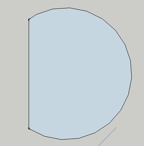
Here's something that just hit my desk. A 40' D-Shaped revolve. Essentially it is a circle with a third of it chopped off. It needs to rotate all the way around. Multiple times. Both directions. Multiple stopping points. Before I tell the designer he has to be joking... I thought I'd see what some prevailing thoughts were. Pretend there is about 10k to throw at this, there probably is.

I've done smaller revolves that were controlled from a trap room. Basically just run the axle straight through the deck/hubs/sprockets/idler/motor....shazam. But this beast is going to weigh (and I haven't worked all these numbers perfectly yet) in the neighborhood of 6,000lbs.

So I imagine the axle drive is theoretically possible, but it seems to me the gear ratio is going to have to be phenomenal. If not to get the thing moving, then definitely to get it to stop. I'm thinking I might need an auxiliary means of braking.

Lastly, since it's d-shaped, the upside down castors on the deck is out. Does anyone have any genius suggestions to this end? One loco-thought I had was an air castor system. The thought being that it could be used as an e-stop as well. But then god forbid something goes wrong with the hoses or there is a leak....and it's under a revolve under thousands of pounds of scenery....yeesh....

thoughts?
 
Here's something that just hit my desk. A 40' D-Shaped revolve. Essentially it is a circle with a third of it chopped off...
....Lastly, since it's d-shaped, the upside down castors on the deck is out.

Ok so it's not "D" shaped it's more of a "pacman" shape ? I'm not certain I understand whay the upside down caster system wouldn't work. Nor, for that matter, why a rim drive via chain or cable wouldn't work. Maybe a thumbnail?
 
Screen Shot 2013-01-26 at 5.54.01 PM.png

Not pac-mac. A circle with flat edge. You are right that the upside down castors would work for the inner portion, but not for the edge. Rim drive won't work obviously. I have given some thought to a cable or chain but that would be complicated as well. There are times when: 1) the flat edge is upstage a rectangular wagon is attached to it 2) it rotates around to reveal the scene change. Any outside the box thinkers?
 
Manual stagehand power is not a bad idea. However, if automation/motor drive is required/called for because of esthetic/visual/economic/etc reasons, a rim drive is a viable option. The "rim" would be a false rim built under the table with a radius determined by the distance from the center of the flat side to the center point. I do not recommend a friction drive but rather a pinch drive or a roller chain drive (my choice) as the weight of the table and the reduced torque from the smaller radius would produce a significant horizontal loading on the friction surface and thus the revolve pivot pin. A Central axle drive is still viable, depending on the speed/time required for the unit to move from one position to the next.
 
Thanks for these suggestions MPowers and BrianWolfe. For Brian, I had thought about this option, but I worry that the amount of friction necessary to drive the wheel might be hindered by this setup. I have been in touch with Creative Connors and even with an edge drive option for a 40-foot circular revolve of this weight they suggest two drive wheels.

MPowers: I like this option better, and had also thought of it....I know it is probably the most viable (the other front-runner is a false stage the height of the motor, a 40-foot circular revolve that is flush with this false deck, and then upon that the d-shaped revolve) Both make me cringe at the amount of time and material, but that is why we TDs have dart-boards with our set designers' faces on them, right? Also, by pinch drive do you mean two drive wheels mounted 180deg. opposite each other?

FWIW: The stagehand drive option is almost certainly not an option for aesthetic reasons. I may float it to the director to see if there is some way that a team of chorus members can motivate these scene changes, but that is a snowball's chance.....

Thanks for the suggestions, keep them coming if you have them.
 
I've told the story before about being pissed at a Lyric Opera of Chicago production that had a chorus of ninjas pulling ropes to move the turntable. Found out later it was completely motorized, and the ninjas were just for aesthetic value. To this day, I'm still confused by that one.


Sent from my iPhone using Tapatalk
 
.............. Also, by pinch drive do you mean two drive wheels mounted 180deg. opposite each other?................QUOTE]

A Pinch drive can be two wheels or three. The last one I designed, engineered and built was for a semipermenant 36' diameter revolve for Wildwood Park for the Performing Arts, just outside of Little Rock, Ar. It was a large table, designed to handle grand opera and turn smoothly with a cast of 1,000s and lots of heavy scenery. So it was built perhaps a tad bit beefier than you need. It was a three wheel pinch drive. The drive surface was a 1/4" thick 6" wide steel plate, curved to 18" less than the radius of the turntable. It was welded on edge to the underside of the frame for each segment. Two 14" lawn tractor tires were about 18" apart and driven by a #80-2 double strand roller chain, powered by a 10HP VFD motor. These two tires rode on the outside of the drive rib. The third tire was an idler that rode on the inside of the rib in between the two driven tires, so the three tires formed a triangle. All three tires were mounted on sliding brackets with a 1" threaded rod that could adjust them in or out to adjust the pinch pressure. A major advantage of the pinch drive is that it puts zero lateral loading on the table and the center pin. As we built a 70 amp, 12 circuit pancake slip ring into the center of the table, the zero loading made a big difference in the performance of the slip ring.

I have also seen pinch drives with the drive surface flat and the drive wheels one above and one below. Of course this will use smaller diameter drive wheels because of clearance issues. This is very effecient for low speed constant motion tables like a revolve at an auto show, 20' diameter, 2 rpm and runs for hours at a time.

This could be two wheels on opposite sides of the table I suppose, one driven and one idler. I'm not sure if this would be much dirrerent than a straight friction drive. The drive surface would still have to be strong enough to handle the pressure of the wheels pushing against them, but the opposing wheels should remove lateral pressure on the center pin. Hope this helps.
 
Last edited:
15 or so years ago I built a pair of shaft drive units based on a design from a TD&T article (which I can no longer find) each with a 1hp motor and a 40:1 reducer. We have used them under various wagons and turntables, sometimes alone, and sometimes in pairs--the motors run close enough to sync that it does not seem to make a difference in the drive profile, so long as the powering cables are the same length. I don't completely understand this but my motor supplier says it's critical. We also fabricated a beefy version of the pipe-in-pipe pivot using 2 sizes of mechanical tubing that fit--I think 3" in 4", with 1/4" plates for top and bottom that we also use under a stock 34' diameter steel turntable--normally a 3hp 30:1 rim drive. This allows for feeding power and other cables to the table itself, or in this case to the motor. You will probably need more power than that, given your loads. As a less expensive alternative to a commutator I have used these with great success Replace Sliprings with Mercotac Model 230
 

Users who are viewing this thread

Back