Mounting I-Cues

This is correct. DO NOT try to run power though a 5-pin cable. Aside from the 22awg wires not being rated for it, there are so many other bad things that could happen, as @venuetech mentioned. Use a proper 24VDC power supply and proper 4-pin cable. Do it right, or don't do it at all.

This is just a terrible idea!!! Think for a second about what would happen if you connected the +24VDC and -VDC together onto one pin, then supplied power.
...
...
...
Okay, that was more than enough time. Not good, right?! If you don't know the answer, I don't think you should be doing something as simple as connecting a cable to a power supply and a device.
And this is before we even get to considering the different current handling ratings of the pins between the the larger gauge contacts in the four contact connectors and the smaller contacts in the fives.
No! Wrongo!! Don't do it!!! Bah humbug!!!!
Toodleoo!
Ron Hebbard.
 
This is just a terrible idea!!! Think for a second about what would happen if you connected the +24VDC and -VDC together onto one pin, then supplied power.
That doesn't make any sense; why would I do that?

1: ground
2: data
3: data
4: V+
5: V+

Five conductors. At the fixture end the two V+ conductors are tied to pin 4.


Now any well designed RS-485 circuit should have a transceiver that can handle that much common mode voltage on those pins. But again, I don't have any intelligent fixtures at all - just the cabling that's run and I'm trying to work with what I've got to get what I want.
 
I feel like you all are trying to tell me something...


When I embarked on this endeavor I was unaware that XLR4 was even a (quasi)standard for DMX + power. Now that I know, I'll adjust my plans accordingly. Honestly, I hate non-standard installations, so...
 
Except that the I-Cue (and other units that use the color scroller type cable) expect to see V- on pin 1 and V+ on pin 4, data - on pin 2 and data+ on pin 3 with the shield connected to the connector shell.
RoscoI-Cue.PNG
 
That doesn't make any sense; why would I do that?

1: ground
2: data
3: data
4: V+
5: V+

Five conductors. At the fixture end the two V+ conductors are tied to pin 4.


Now any well designed RS-485 circuit should have a transceiver that can handle that much common mode voltage on those pins. But again, I don't have any intelligent fixtures at all - just the cabling that's run and I'm trying to work with what I've got to get what I want.
What you are suggesting is not safe and should not be done. I don't know how else to say that in a way that @microstar, @JChenault, @venuetech, and @RonHebbard have not already said. Just don't do it!

So, in your pin-out where is the -VDC? There has to be a completed circuit for there to be power. Also, pin 1 is not ground and should not be mistaken for it. It is shield. Pin 2 is -data and pin 3 is +data. If pins 4 and 5 are used, they are -data(2) and +data(2) respectively. The picture @JohnD posted is correct for most 4-pin cable. Like I said, do this right or don't do it at all!
24VDC is a lot for a dmx transceiver. I would expect one to blow quite spectacularly with that much hitting it.

XLR4 was even a (quasi)standard for DMX + power.
It isn't a (quasi)standard for DMX + power. It is THE standard.

All said and done. I'm glad you've come to CB for help. That is what we are here for. Please don't get discouraged by the answers you are getting, but instead take the opportunity to learn more.
 
What you are suggesting is not safe and should not be done. I don't know how else to say that in a way that @microstar, @JChenault, @venuetech, and @RonHebbard have not already said. Just don't do it!

So, in your pin-out where is the -VDC? There has to be a completed circuit for there to be power. Also, pin 1 is not ground and should not be mistaken for it. It is shield. Pin 2 is -data and pin 3 is +data. If pins 4 and 5 are used, they are -data(2) and +data(2) respectively. The picture @JohnD posted is correct for most 4-pin cable. Like I said, do this right or don't do it at all!
24VDC is a lot for a dmx transceiver. I would expect one to blow quite spectacularly with that much hitting it.


It isn't a (quasi)standard for DMX + power. It is THE standard.

All said and done. I'm glad you've come to CB for help. That is what we are here for. Please don't get discouraged by the answers you are getting, but instead take the opportunity to learn more.
And it is THE standard so that people dont accidentally run power thru dmx to devices that cannot handle it.
Its been the standard for years for devices like that too.
Iqs, colour scroller, dmx controlled iris kits.
 
Not to be a jerk, but according to DMX512A, rev 2013, "The alternate connector shall not be any type of XLR connector." Therefore it may be a de facto standard, but certainly not du jure. (likewise XLR3)

Which is probably why it was foreign to me since I've never worked with these devices yet. Until I read the Rosco manual the second time I completely missed the XLR4 and assumed it was XLR5 with V+ on pin 4 and pin 5 unused (which I thought was weird).

I will be following everyone's advice (thank you) and making a power injector that has XLR5 male on one side and XLR4 female on the other side. Then having XLR4 at both ends off the cable running to the bar. If I ever want a line powered device up there, I assume the conventional thing to do is make an XLR4 male to XLR5 female that drops pin 4?
 
Glad to hear you are getting things figured out. I'm still slightly concerned about a couple things though.
I have power supply at the dimmers that injects +24VDC onto pins 4&5.
I don't understand where your power is coming from and why it would have two +VDC lines. Where is the -VDC coming from?

... making a power injector that has XLR5 male on one side and XLR4 female on the other side. Then having XLR4 at both ends off the cable running to the bar.
I'm very confused about what you are attempting to do here. Can you explain it better? Maybe a simple drawing. I just don't want you damaging anything.

the conventional thing to do is make an XLR4 male to XLR5 female that drops pin 4?
ABSOLUTELY NOT!!! Do not make any cables that have XLR4 and XLR5. That is as bad an idea as a suicide cable. XLR3 and XLR5, okay. XLR4 and XLR5, NEVER!

http://www.apollodesign.net/smart-power-200w-power-supply.html
Thats the conventional thing to do. You have something like that. Has DMX in and thrus and 4 pin ins and outs.
Making homemade wires and adapters is just asking for problems and could very well void any warranty on the I- Cues.

Or if you only have 1

http://www.apollodesign.net/smart-power-75w-power-supply.html

Something like that.
Also, this. Thanks @DeadCheerios! FYI, the I-Cue uses 17 watts, so the 75W supply could power 4 units.
 
ABSOLUTELY NOT!!! Do not make any cables that have XLR4 and XLR5. That is as bad an idea as a suicide cable. XLR3 and XLR5, okay. XLR4 and XLR5, NEVER!
Never say never! There is one way to safely make an XLR4 to XLR5 cable. However, it is still not a good idea since there are better ways that are correct to do the things that might necessitate one. I'm hesitant to even say this for fear someone will do it wrong and damage something, but against my better judgement... You could make an XLR4 to XLR5 cable, using DMX cable, NOT scroller/data cable, that only had pins 2 & 3 connected. That way there is no potential for power. An XLR5 to XLR4 cable would be useless though.
 
Never say never! There is one way to safely make an XLR4 to XLR5 cable. However, it is still not a good idea since there are better ways that are correct to do the things that might necessitate one. I'm hesitant to even say this for fear someone will do it wrong and damage something, but against my better judgement... You could make an XLR4 to XLR5 cable, using DMX cable, NOT scroller/data cable, that only had pins 2 & 3 connected. That way there is no potential for power. An XLR5 to XLR4 cable would be useless though.
Yeah, that's exactly what I had in mind.

As far as the power supply and XLR5 -> XLR4 I'm (re)making - it's the same wiring as the SmartPower 75.
 
@Chris Pflieger, If you do decide to make your own power supply I would recommend getting a DMX splitter such as a Enttec D-Split. The d-split is optically-isolated so that protects the rest of your rig from any cable/power issues. I have never been able to justify what I consider the high pricing of something like the i-cue 50w power supply and others in that class, that sells for close to $175 and has less than $30 of parts involved. I purchased a long 4pin scroller cable that had the larger gage power conductors and then cut that and carefully remade those to the lengths needed.

there may well bee some other splitter on the market that has the same features, it is just that I happen to have worked with the D-Split.
 
Yeah, that's exactly what I had in mind.
But from the quote below, that's not what it sounds like you are doing. The cable I mentioned is only good for getting data ONLY from a 4-pin output to a 5-pin input. You are needing a 5-pin output to 4-pin input.

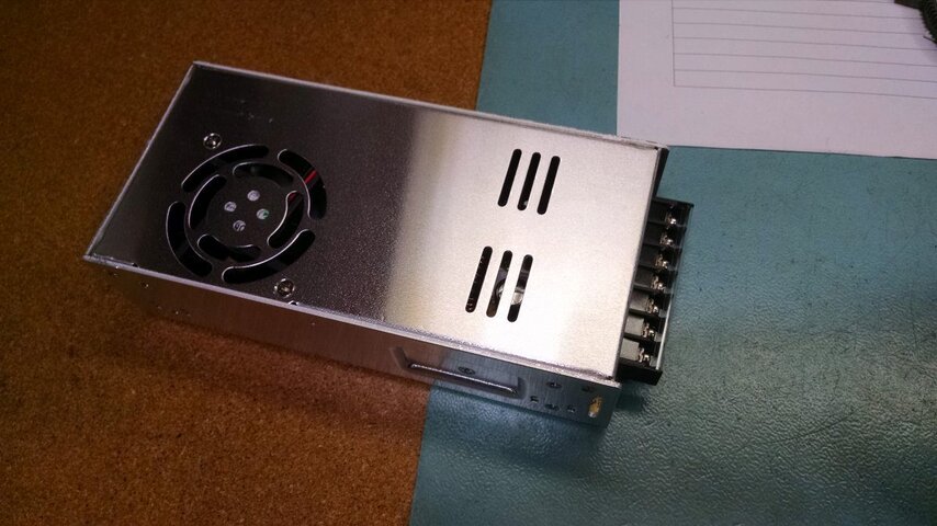
I'm still a little concerned about the power supply. Is it the same type as the Smart Power 75W? I'm inclined to think it is since you said sealed. If not, are you talking about a power supply pack that mounts inside of something, like the attached picture? If so, once again, be sure you are using an appropriate cable to supply AC. Also, will it be inside of any type of housing? Those packs tend to get quite warm and also have semi-exposed terminals. It would be best if it was protected so that someone couldn't just walk up and touch it.

As far as the power supply and XLR5 -> XLR4 I'm (re)making - it's the same wiring as the SmartPower 75.
Technically, you aren't really making an XLR5 to XLR4 cable. You are making a strange combining wye cable. Just be sure you wire it up properly. Your 22AWG twisted pair wire going between the XLR5 and XLR4 should only have pins 2 & 3 connected one-to-one on both connectors. (The cable we use is Belden 8451 or similar. It has the proper twist and a good foil shield. The drain wire is not used and should be clipped off. That cable is used because it meets DMX specs and it is small enough that it will easily fit into the XLR4 with the second wire, whereas a normal DMX cable would not fit with the second wire.) You need to be sure that the cable you are using between your power supply and the XLR4 is of proper guage (if the power supply isn't similar to the SP 75W). The +24VDC wire goes to pin 4 and the -VDC wire goes to pin 1. If you follow all of that, you should be good. Just don't forget to slip the XLR4 back shell over both cables before doing any soldering.
 

Attachments

  • power supply.jpg
    power supply.jpg
    125.8 KB · Views: 116
@Chris Pflieger, remembering that you mentioned not really knowing about 4-pin devices before this, I figured it would be good if I gave some more information about it. Most of what I'm going to mention is just good practice for best results on a full load, but YMMV.
You can't run 4-pin cable thousands of feet like you can DMX cable. Really you should limit your cable-feet to about 200. That does include a return line. It is best to keep your furthest unit from the PSU within 100 cable-feet. The voltage drop can be a bit much beyond that. Use the shortest cables available between the PSU and first device and between the daisy-chained devices.
"What's that about a return line?" I knew you'd ask! A return line is an additional cable run from the output of your last device in line back to the return on the PSU. (In your setup, and when using a PSU like the SP 75W, this is not possible.) This does two things. First, it completes the DC circuit. That means you will have less of a voltage drop and more consistent power across all the devices in the chain. Second, it terminates the data. Most PSUs have a 120 ohm terminator across pins 2 & 3 of the 4-pin return jack. Those two things should be all the reason you need to run a return line when possible.
I know there are likely people reading this that have been using 4-pin devices for a long time and have never heard of running a return line. While most PSUs are set up to accommodate the return line, Apollo seems to be the only PSU manufacturer that (pro)actively recommends it.
There ya go! The more you know!
From the perspective of prudent power distribution, including the return line brings you into line with what electricity companies do when using loop distribution to distribute power within towns and cities. To boringly elaborate: If you feed a group of loads from one end, your worst voltage drop is at the far end. If you feed it from both ends, your worst case voltage drop a, is less and b, is in the middle, assuming all of your loads are equal and all of your cables are of equivalent gauges.
I'll quit blathering now and relinquish the lectern.
Toodleoo!
Ron Hebbard.
 
@Chris Pflieger, If you do decide to make your own power supply I would recommend getting a DMX splitter such as a Enttec D-Split.
We have a optical splitter - one output for each bar. Off hand I don't know the brand - not a cheapy one, I know that.


OK, at this point, I just say, "thank you all for the help - I got now." I'll take your industry wisdom and my EE training and experience and make it right.

PS - I'll get some Apollo cables to link the two ICues. :)
 
Last edited:
They're up and running!

I haven't switched the power supply yet - I just unplugged it when I left for the night. I think I'm going to install a relay control that switches on and off with our audio system - no need for lights without sound and it's one less thing to forget to turn off.


One thing I found out - the original installers used one pair of wires for pins 1 and 2 and then one wire from the second pair for pin 3, pins 4 & 5 are unconnected, shield unconnected at both ends. :mad:
 

Users who are viewing this thread

Back