Musician severely shocked by microphone.

Okay. so why are the ceramic death caps installed in the first place? They are WAY too small for any kind of ripple filtering. I always assumed they shorted RF to ground to reduce the chance of radio interference. I now understand the importance of removing them, but I'm wondering what the negative consequences might be of removing them. Does connecting the chassis to ground accomplish the same thing as the caps used to accomplish, thereby making them unnecessary when a three-prong cord is added? This is an interesting issue that includes a lot of old equipment from old PA amps to CB radios. I've seen those caps installed in a lot of old equipment, not just guitar amps!

Here's a very good article that will answer your question...

David Lamkins - Guitarist - Ground switches and "death caps"
 
I can personally attest to the fact the 110v is enough to cause a person to not be able to let go of an object... as happened to me 12 years ago when a failed cable energized the metal casing of the multi connector I was plugging in. I was not able to let go, and only released it after tackled by a co-worker... (I also shat my self... and had no say in the matter)

I also witnessed this week, a performer being shocked through a mic during a rehearsal.... It seems a mis-wired L6-20 cable was sending 110v through a lighting fixture chassis... through its clamp, and ito the stage... the barefoot musician steped on a metal stage seam, and touched the mic... which became the best path to ground.

In summary... it does happen!
 
There is more information over at soundforums.net.
Bad mic shock
Several of the posters there have worked in that club and have reported wonky power.
 
I thought that by using an inexpensive 3 LED tester, one could determine if the outlet was wired correctly and avoid the dreaded "wonky power". Then I watched this video. I'm totally confused as to why the tester didn't indicate a problem with the 3rd outlet.

To view this content we will need your consent to set third party cookies.
For more detailed information, see our cookies page.

Reverse Polarity Bootleg Ground Testing - YouTube
 
Last edited by a moderator:
Because the outlet *is* wired correctly (meaning that the ground pin and the wider neutral pin are at the same potential). The source has been reversed, putting the normally grounded pins, connected together with the bootleg connection, at 120 volts. (But you already knew that). The tester doesn't know about the reversed source. It only understands that the ground and neutral pins are at the same potential and approves the receptacle.

Very informative video.

Laryn

Guys, I'm Mike Sokol - The guy who created the RPBG (Reverse Polarity Bootleg Ground) video you just mentioned. I've known about this mis-wiring condition for about 40 years, but never really thought about it too much until I tried to design my own high-current 3-light outlet tester using 100 watt bulbs to load the safety ground properly. As I was drawing and tracing the diagrams, I noticed that one very dangerous condition would not be detected by any 3-light tester, something I now call an "RPBG" or Reverse Polarity Bootleg Ground. So I built a test outlet and tried one to confirm that a 3-light tester would be fooled. I also tried it with a $300 Ground Loop Impedance Tester (SureTest Analyzer), which the manufacturer assured me would detect an RPBG, but I was sure wouldn't detect one. And, of course, after trying Ground Loop Testers from Amprobe, Extech, and others ranging from $250 to $800 in cost, I confirmed that NONE of the them could detect an RPBG. Also, none of their engineers even knew that an RPBG could exist or that their testers would NOT detect one. That is, until they duplicated my experiment and were convinced.

9576-musician-severely-shocked-microphone-bootleg-ground-demo-b.jpg


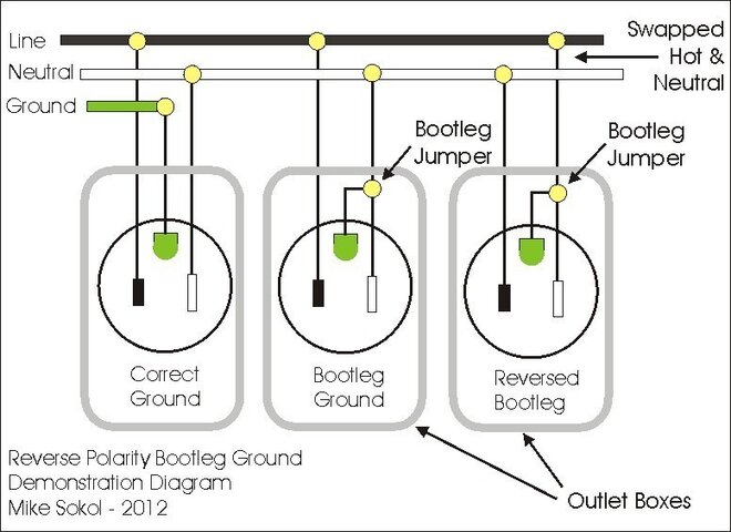
Historically, many RPBG outlets were accidentally created in the 70's and 80's when houses and stages were being "upgraded" to grounded outlets. But since building code prior to the early 70's required no ground wire, the electricians would rig up a quick fix by putting a jumper between the ground screw and the white/neutral screw on the outlet itself. Though a violation of modern electrical code, it was a quick fix done in perhaps millions of outlets around the USA during the 70's and 80's, and even right now. While a correct polarity bootleg ground (CPBG) isn't immediately dangerous, if the hot and neutral are accidentally swapped inside the walls (very easy with black/black knob & tube wiring), then the Hot slot of the electrical outlet is at earth-ground, while both the neutral slot and ground-slots are sitting at a full 120-vots. What's really crazy is that there's no indication that anything is wrong because the gear will still operate normally. That's right, your amp or mixer will turn on properly, won't hum any more than normal, and there will be no sparks or blue glow like in the movies. However, the amp chassis, and anything connected to it like your guitar or microphone, will be energized to a full 120-volt with 20 or more amperes of current.

There's two situations that make an RPBG outlet highly dangerous. If you plug stage amp with a grounded power cord into an RPBG, then your guitar is electrified. If touch a grounded microphone with your lips while touching the guitar strings, then you'll receive a potentaily deadly shock (electrocution) from the guitar, but you'll probably blame the mic since that's what "grounded" you.

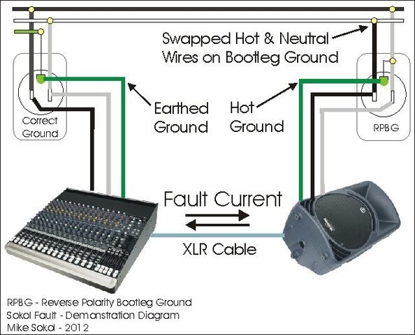
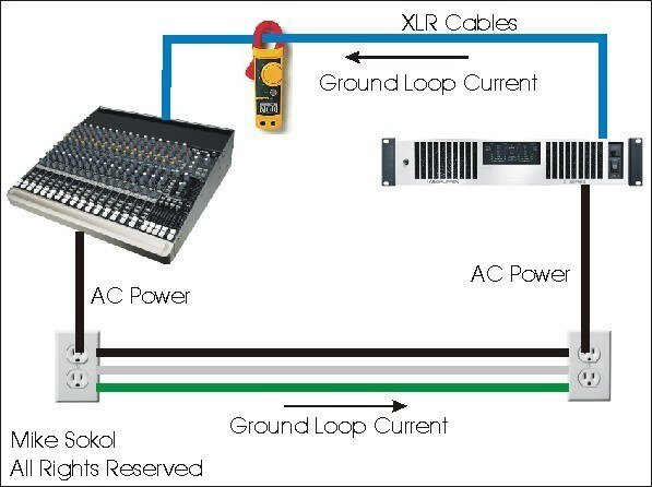
The second situation is more gear dangerous. If you plug your power amp rack into an RPBG outlet on stage, then plug your mixing console into a properly grounded outlet in the back of the room, as soon as you plug an XLR cable between them there will be a full 20 amps of current flowing through the shield of the cable (or snake) which will turn cherry red and burn right in front of your eyes. I've seen digital mixing boards and active monitor speakers destroyed in a second. And if you connect them using a DI box for ground-loop hum control, swithing the ground-lift to "ground" can cause your DI box to meltdown internally in your hand.

See the diagram below for a clear picture of the XLR cable current path between a cross-connected RPBG outlet and correctly wired outlet.

9575-musician-severely-shocked-microphone-rpbg-sokol-fault-640.jpg


The only quick way to check for an RPBG outlet is by using a Non Contact Voltage Tester (NCVT) such as a Fluke VoltAlert I'm using in the video. Please contact me if you have any questions or comments as I'm beginning to write a 10-part series covering hums, buzzes and shocks for a pro-audio installation magazine. Your input will help me be sure I'm covering all the right topics.

Mike Sokol
[email protected]
No Shock Zone
 

Attachments

  • RPBG Sokol Fault 640.JPG
    RPBG Sokol Fault 640.JPG
    68.9 KB · Views: 812
  • Bootleg Ground Demo B.JPG
    Bootleg Ground Demo B.JPG
    70.1 KB · Views: 856
Last edited:
Or by metering between ground and the two blades. If one cones up 0 you have a problem.

That test wouldn't work because G-N should be 0v in a correct system as well as in a RPBG scenario.

The caveat to that is that G-Earth and N-Earth should also be 0v, but in a RPBG scenario, they would actually both be energized to 120v relative to earth ground, but because of the nature of the fault would appear to be at 0v relative to earth.

The key here is to differentiate 0v from meaning that something is harmless and unenergized. There are linemen who latch onto the high-voltage conductors they are servicing to work on the transmission lines while live. Though they themselves are 0v relative to the very high voltage lines they are servicing, they are still energized to many thousands of volts relative to earth. The "trick", if you want to call it that, is not to come in contact with ground or conductors at any other potential.

At the risk of grossly oversimplifying this, if you're at 50kV and only come in contact with that 50kV source, you're fine because you're at 0v relative to the source and no current flows through you. If you're at 50kV and come in contact with earth, a lot of current will surge through you.

The problem with an RPBG scenario is that the only way to tell it exists is measure G-Earth, N-Earth, or use a non-contact voltage detector that will sense the ground and neutral conductors are energized -- even if they measure 0v between each other and 120v relative to the hot conductor.

The point of all of this is to understand that the ground pin is not always connected to ground, and that the hot and neutral conductors are not always correctly wired. These conditions can exist for a breathtakingly long time before the stars align just long enough to get someone hurt or start a fire.

Lighting is a good example of where this could be bad. Say you're in an old room that didn't originally have ground wires. Someone decided to add grounds by connecting the ground pins of receptacles to the neutral wires, but mistakingly wired the neutral pin to the hot conductor and hot pin to the neutral conductor.

For 10 years you have a theatrical light with giant metal fixture bodies connected to an RPBG circuit. The pipe it hangs on is mounted to concrete so it isn't grounded either. The light always turned on so you didn't think much of it. After all, if someone did check, they'd find 0v N-G and 120v H-N and H-G, which is what you'd expect to find. What you wouldn't notice is that G-Earth happened to be 120v as well...

On this particular day, you happen to using one hand to focus the light while using your other hand to brace yourself on a metal railing --- you're barbecued. The fixture's body is energized to 120v relative to earth though it would've appeared to be 0v to ground. When you touch one hand to an unpainted part of the fixture and another to an unpainted part of the railing, the freak conditions exist to create catastrophe. I say freak, because usually fixture bodies are painted.

That said, I've seen a lot of lighting fixtures where the wires are loose in the connectors and the ground wire comes dangerously close to contacting the hot wire. If the right conditions exist, all you need is for someone to come in contact with an unpainted metal part of the fixture body while somehow also being grounded themselves to cause an electrical current to flow from the fixture body, through a person, and into something grounded.

This is all to say that proper grounding is important for a safe working (and living) environment and your meter can tell you the truth but be deceptive to you all at the same time. Whether or not something is properly grounded may or may not be apparent, but nonetheless the consequences of improper grounding can be grave. Such faults can exist in devices as well as in building wiring. Just because something seems to have been working for a long period of time does not necessarily mean that it does not have faults which, if the stars aligned, could produce fatal results.
 
Last edited:
This is all to say that proper grounding is important for a safe working (and living) environment and your meter can tell you the truth but be deceptive to you all at the same time. Whether or not something is properly grounded may or may not be apparent, but nonetheless the consequences of improper grounding can be grave. Such faults can exist in devices as well as in building wiring. Just because something seems to have been working for a long period of time does not necessarily mean that it does not have faults which, if the stars aligned, could produce fatal results.

Mike N

You're 100% correct. I've recently found an outlet in my house that was "upgraded" in the 80's with a bootleg ground. But since my house was built in 1926 with K&T (Knob & Tube) wiring, the electrician accidentally swapped the Hot (120-volts to earth potential) and Neutral (0-volts to earth potential). Now, I've been in the house for 25 years and never knew this, since I had originally tested all the outlets with a 3-light tester and it checked out as OK. However, my teenage boy recently used a Fluke VoltAlert to test all house outlets for RPBG conditions, and announced that the air conditioner in the window was "hot". Now, standing on a hardwood floor there was little chance of getting shocked, but if he would have plugged his printer into that outlet, and his laptop computer into the correctly wired outlet on the adjoining wall, a USB cable would have destroyed his new laptop computer. There's a professor at the University where I teach that did exactly that. But in that case he paid a licensed electrician to put in a "grounded" outlet, and the guy did a bootleg ground to save time instead of running a new ground wire, and it turned out to be an RPBG. Bad things happened when he plugged a printer into that outlet that was connected to his computer running his Protools editing system, to the tune of $6,000 or so.

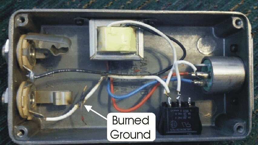
Also, if you want to see what happens to a DI box used to feed audio between a piece of gear plugged into a stage outlet with RPBG and a correctly wired outlet at the mixing console position, take a look at the following picture.

9578-musician-severely-shocked-microphone-imp-2-burned-ground.jpg


This pic was sent to me from my tech buddy at Whirlwind. A customer claimed that their IMP2 DI box was defective because it overheated and somehow burned up a digital mixing console and two Mackie active monitors. You'll see the melted ground wire that occurred when the LIFT switch was GROUNDED. Interestingly, I talked to Whirlwind about this who said their transformers were tested to 300 VAC common mode. That means that if you hooked a IMP2 between gear plugged into RPBG and properly grounded outlets, it would work perfectly until somebody UN-LIFTED the grounding switch. Yikes!!! This happened in a older church building where a volunteer DIY guy "upgraded" the stage outlets to grounded receptacles and did bootleg grounds, at least one of which turned out to be an RPBG. So this was an accident just waiting to happen. Plugging a guitar amp into that outlet would have energized the chassis and guitar to 120-volts with a full 20-amp current capability. Touching a mic and guitar at the same time would have resulted in a serious shock, or even death by electrocution. They were "lucky" to find the RPBG by plugging in gear that blew up. Oh, the reason they blew up two Mackie speakers was that after the sparks flew the first time, they got a second (brand new) Mackie speaker out of the box and plugged it in to try. Blew that one up too, in addition to the outputs on the digital board. I think that was $6,000 in damages as well. So $6K in damages appears to be the magic number for RPBG connected gear.

Mike Sokol
 

Attachments

  • IMP-2 Burned Ground.JPG
    IMP-2 Burned Ground.JPG
    104.6 KB · Views: 728
Last edited:
That test wouldn't work because G-N should be 0v in a correct system as well as in a RPBG scenario.
Also correct. You can meter between H-N (120-volts), H-G (120-volts) and G-N (approx 0-volts) and an RPBG outlet will measure correctly. Interestingly, one hint that a bootleg ground was done is when G to N measures exactly zero volts with a load on the outlet. Since there's always a voltage drop in a neutral wire carrying current, an outlet with a properly isolated safety ground should measure between a few tenths and up to 5 volts between Ground and Neutral. That's because the safety ground should stay close to earth potential, while the neutral wire will have the same voltage drop as the hot wire, but with inverted phase. So an outlet with a voltage drop from 120 down to 110 volts will lose 5 of those volts on the hot wire and the other 5 volts on the neutral wire. Since they're 180 degrees out of phase, that adds up to the 10 volt drop. Measuring between the safety ground and and the neutral contacts will show 5 volts, exactly as predicted and perfectly normal. So if G to N measures zero volts with load on the outlet, then the ground screw must be bootlegged to the neutral screw.

Interesting, isn't it? ;)

Mike Sokol
 
As someone who has seen NFG in person quite a few times (Yes, I'm a fan...what of it? :p), I have always seen them performing with SM58 vocal mics. There is no way they were "shocked" by the mic without ability to let go. This is just flat out impossible. If the singer was shocked, it was through some other means (such as the amp possibly). In general, the whole thing sounds fishy

Well, I do believe it was a problem with the guitar amp plugged into an improperly grounded outlet or extension cord. And yes, if he grabbed a grounded SM58 mic he wouldn't be able to let go. And here's why. Your body with wet hands has about 1,000 ohms resistance. Now, if you have 120 volts potential on one hand (your hand on the guitar strings) and 0 volts on the other hand (your hand on the mic) then Ohm's law shows your getting 120 mA (milli-amps) of current through you. At approximately 20 mA of current all your muscles will go into full tension, and since your hands have more muscles trying to clasp your fingers into a fist than release your fingers, you'll "grab" onto the electrified object (in this case a microphone) and can't let go. That's why old electricians will brush a knuckle across anything potentially energized, since any voltage will make their hand "jump away" from the energized object. If you touch an energized mic with the palm of your hand, you'll automatically "grab it" and can't let go. Now remember, in this case the microphone was probably at 0-volts with respect to earth ground and the guitar could have been at 120-volts. But from the performer's perspective, it "feels" like the mic is shocking you. That's because it's all about the differential voltage, and nothing about the common-mode voltage. As noted earlier on this thread, that's why a power line guy can touch a wire with thousands of volts and not feel it, as long as he doesn't touch anything else that's grounded. It's the pigeon on the power-line scenario. Birds rest on uninsulated wires with hundreds of thousands of volts on them, but never feel a thing. Now if they happen to touch another wire with a wing tip or perhaps a metal structure that's grounded, then there's a big boom and a lot of burnt feathers.

Mike Sokol
 
Since there's always a voltage drop in a neutral wire carrying current, an outlet with a properly isolated safety ground should measure between a few tenths and up to 5 volts between Ground and Neutral. Mike Sokol

Well, almost. For there to be any voltage drop on a conductor, there has to be current flowing. V = IR If there is no load on the circuit, you could measure 0 Volts on a properly wired circuit with a ground wire. A digital voltmeter does not present enough load by itself to measure significant voltage drop.

While I don't want to diminish the importance of RPBG safety, we should also recognize that most large public buildings, at least those built post-war, are wired in metalic conduit. It's nearly impossible for RPBG to happen with conduit, because the receptacle ground is bonded by the screws and mounting ears into a metal box which is grounded by the conduit carrying the wires. In fact, it is perfectly legal for the conduit to be the only grounding conductor, instead of a wire. RPBG is much more likely to be found in residential and smaller public venues like bars and churches. In those places, I would be wary about checking power. Not so much in large auditoriums and schools.
 
Well, almost. For there to be any voltage drop on a conductor, there has to be current flowing. V = IR If there is no load on the circuit, you could measure 0 Volts on a properly wired circuit with a ground wire. A digital voltmeter does not present enough load by itself to measure significant voltage drop.

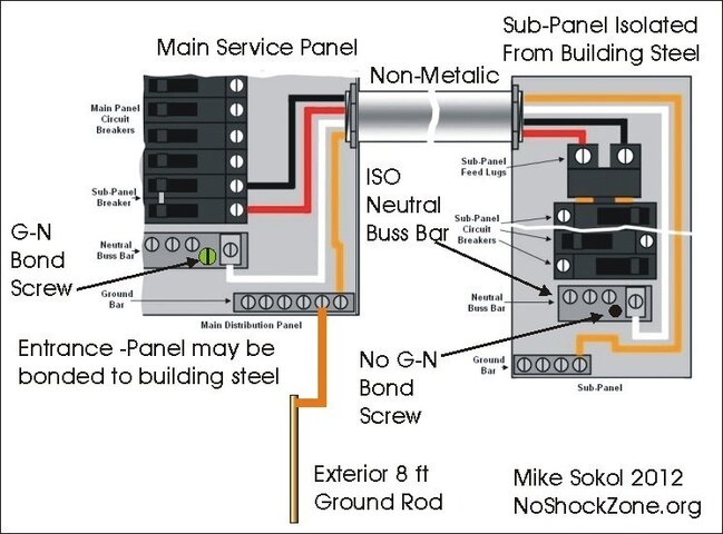
That's true, but I'm talking about real-world situations where there are nearly ALWAYS some other current draw on a sub-panel or branch circuit. You'll only read zero volts between Ground and Neutral if there are no other current loads in those legs, or if you're on a home-run back to the service panels G-N-E bonding point. That almost never happens. I know because I routinly measure G to N voltages in all types of buildings, and there's nearly always a few millivolts difference between G and N. See below for a diagram from my No~Shock~Zone class. All modern building grounds are supposed to be isolated from the building frame (except at the point of entry for the service panel) and maintain separated grounds and neutrals in each sub-panel. So ANY current draw on a sub-panel will cause some voltage differential while measuring between ground and neutral.

9579-musician-severely-shocked-microphone-g-n-bonding-subpanels.jpg


While I don't want to diminish the importance of RPBG safety, we should also recognize that most large public buildings, at least those built post-war, are wired in metalic conduit. It's nearly impossible for RPBG to happen with conduit, because the receptacle ground is bonded by the screws and mounting ears into a metal box which is grounded by the conduit carrying the wires. In fact, it is perfectly legal for the conduit to be the only grounding conductor, instead of a wire. RPBG is much more likely to be found in residential and smaller public venues like bars and churches. In those places, I would be wary about checking power. Not so much in large auditoriums and schools.

That's very true. But conduit grounds cause something else very insidious. Since by definition they're bonded to the building steel in multiple places, they nearly always cause ground loop hums in sound gear. That's due to the fact there are huge currents in building steel. In fact, I've personally measured up to 5 volts AC between one side of a million square foot warehouse and the other. I discovered this when we ran coax from the rail dock cameras back to the centralized guard shack. Way too many hum bars on the video until I used the proper isolation baluns in the coax feed. What this means to an A-V guy is ground loop currents between gear connected with non-isolated inputs/outputs plugged into different outlets. Called the pin-1 problem, it's really a building wiring issue that results from the grounds on either side of a room measuring a different voltage depending on system load in other parts of the building. One test I do is meter G to G from the two outlets and watch for any voltage fluctuations as we turn other loads on and off in the building. If the safety ground is contaminated by some electrician double-bonding the G-N bus in a sub-panel (a violation of current electrical code) then you can watch the reflected voltage drop in the various neutral paths of the building.


9580-musician-severely-shocked-microphone-ground-loop-currents.jpg


One really quick check for this is to simply clamp an AC ammeter around the interconnecting XLR cables. If you read more than a few milli-amps of current, then you certainly have ground loop currents. How bad your hum is will depend on if your gear has the "pin-1" problem or not. I find that a lot of basic powered wedges will have noticeable hum at 100 mA of ground loop current, which only takes about 1/10 of a volt difference in safety ground potential between the two power sources. Sadly, this same ground loop hum causes many musicians and technicians to break off ground pins or use dollar ground lift adapters. That's never a good option since the safety ground is there to save your life if something in the gear shorts to the line voltage.

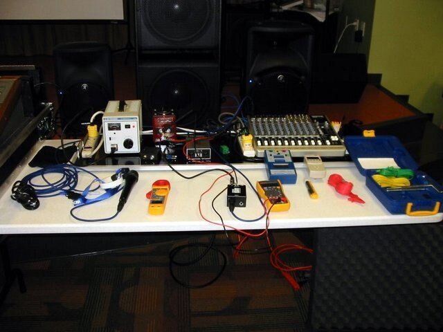
BTW: The reason I'm sure all these numbers is that I've built a test bench that allows me to inject any amount of ground loop current (up to 30 amps) between two pieces of sound gear and measure how loud the ground loop hum is. See below for my portable test bench. The little red box with the big knob on top is a "Glo-Melt" resistance soldering transformer, which is good for up to 2.9 volts and 30 amps or so of current. I have the luxury of being able to simulate and experiment with eliminating nearly any type of ground-loop hum with this system. Too much fun!!!

9581-musician-severely-shocked-microphone-sokol_noshockzone-001.jpg


So you're correct that RPBG outlets don't exist everywhere. However, if you ever encounter one you'll have the knowledge that they exist and should be corrected immediatey.

Let's be careful out there....

Mike Sokol
 

Attachments

  • G-N Bonding Subpanels.JPG
    G-N Bonding Subpanels.JPG
    82.7 KB · Views: 828
  • Ground Loop Currents.JPG
    Ground Loop Currents.JPG
    44.5 KB · Views: 617
  • Sokol_NoShockZone-001.JPG
    Sokol_NoShockZone-001.JPG
    46.4 KB · Views: 502
That's very true. But conduit grounds cause something else very insidious. Since by definition they're bonded to the building steel in multiple places, they nearly always cause ground loop hums in sound gear. That's due to the fact there are huge currents in building steel. Mike Sokol

Let's be accurate here. Conduits contacting building steel does not cause ground loops. Conduits by themselves don't cause ground loops. Ground loops can exist even with isolated ground circuits. I will concede that conduits bonded with structural steel may affect the severity of a ground loop.
 
Let's be accurate here. Conduits contacting building steel does not cause ground loops. Conduits by themselves don't cause ground loops. Ground loops can exist even with isolated ground circuits. I will concede that conduits bonded with structural steel may affect the severity of a ground loop.

I've sent you a PM to discuss this more at length off-line.

I think it's a matter of semantics, so I'm working on new terminology that will allow all of us to better understand and discuss what we mean by the catch-all phrase - Ground Loops.

Mike Sokol
 

Users who are viewing this thread

Back