Rigging Question (!)

Remember that the percentages in that diagram assume some things:

1) The End lift lines are at the END of the batten/truss
2) All lines are perfectly evenly spaced
3) The load is symmetrically distributed onto the batten/truss
4) If in the air it is level (ie not pulled up on one end or slack on one point, causing some points to take more load)

Thanks philhaney! Ding!
 
Derekleffew asked me to repost my original answer and how I came to it.

Original Post:
Assuming I'm correct in what a linear foot is, a 600 pound load on a batten with 5 points would be:

Point A (SR) 58.8 lbs.
Point B (SRC) 171.6 lbs.
Point C (CTR) 139.2 lbs.
Point D (SLC) 171.6 lbs.
Point E (SL) 58.8 lbs.

How I came to my answer:
I was taught that for a 5 point load (our most common usage, conveniently) to calculate it as follows: 10%, 30%, 25%, 30%, 10%, if you add that all together you get 105% of your total load. The reasoning I was taught for this is that it gives you a little bit of play (which could be argued as not the best thing to say to a student) if your load total ends up being slightly off or if your points are not spaced out exactly as the intended formula (see below). However, I have an unhealthy attraction to hemp rigging so I have read a number of books on the subject, in this case I knew that Jay Glerum's book, Stage Rigging Handbook contained the exact percentages for finding the point loads on an evenly distributed batten under the hemp rigging section (for a 5 point batten: .098, .286, .232, .286, .098). Since Derekleffew's wording was, "from five equidistant points," I grabbed my book and used the exact percentages.
 
Props to Arez, DuckJordan, and philhaney. :clap:


... If he means that each pick point is 8 feet apart, and the end pick points are 4 feet from the end of the truss, I believe the weight would be evenly distributed on each pick point ( IE 120# ). ...
Brings up an interesting point: Trusses are usually rigged from the ends, but battens usually have some cantilever.

Anyone know how to (or want to) do the math on a beam/truss/batten supported thusly?

_4'_A__8'__B__8'__C__8'__D__8'__E_4'_


Terms to Google: statically indeterminate structure, theorem of three moments.
 
Last edited:
I know how the 3 members listed above got to their answer, (just did this 2 days ago in mechanics of materials) but i don't agree. the load is evenly distributed and acts on all the reactions equally except for the end 2. just to check i popped the problem into FEA software, and got equal reactions except for the ends which were half. A POINT load with statically indeterminate analysis is the only way to get the load distribution shown in their answers.
Can anyone explain?

the attached picture shows the shear and moment diagram for the new question( 8' spacings with cantilevers). mathematically the loads are all equal because the tributary area of each reaction is equal
8'x15#/LF=120# 120#x5=600#
but the FEA anlysis come out a little differently.

the loads tally left to right as: 126.43;111.43;124.28;111.43;126.43
still = 600# but best i can figure is that the "imperfect" shear stresses are related to the nature of the "pin" reaction and deflections.
 

Attachments

  • Shear and moment.jpg
    Shear and moment.jpg
    42.1 KB · Views: 425
Last edited:
I wasn't going to respond, then Dave posted a link on the SML and I figured I would...I am not a rigger, but I am an engineering student and figured I would try it out

There are five unknowns, therefore we need five distinct equations. We can assume symmetry, that gives us RA=RE and RB=RD. We have the sum of the forces acting vertically must be zero, or 600=2RA+2RB+RC. We have the three moments equation applied to points ABC and applied to BCD.

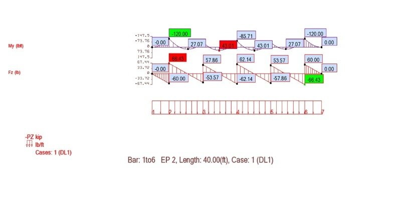
For the three moments theorem, we need to do some fancy math. I worked out the shear and moment diagrams on paper. Bending moments are:
MA=0, MB=10RA-750, MC=20RA+10RB-3000, MD=30RA+20RB+10RC-6750, ME=40RA+30RB+20RC+10RD-12000.you simplify that equation
We can check this result by finding that the bending moment at each end is zero. ME=0, and if you simplify that equation it is the same as the first equation for forces.
For the first three moments calculation:
0*10+2*(10RA-750)*20+(20RA+10RB-3000)*10=1/4*15*10^3+1/4*15*10^3
And for the second:
(10RA-750)*10+2*(20RA+10RB-3000)*20+(30RA+20RB+10RC-6750)*10=1/4*15*10^3+1/4*15*10^3
Solving these yields, according to my calculator, RA=91.1, RB=128.6, RC=160.7

Upon realizing that I am the only one with this answer I ran the calculations again. Here are all the equations:
(VAR is the shear force (V) just slightly to the right side (R) or point (A), the bending moments are calculated by (Area of the triangle)-(Width)*(Displacement below 0))
RA unknown
RB unknown
RC unknown
RD=RB
RE=RA
VAR=RA
VBL=VAR-150
VBR=VBL+RB
VCL=VBR-150
VCR=VBR+RC
VDL=VCR-150
VDR=VDL+RD
VEL=VDR-150
MA=0
MB=MA+10*(VAR-VBL)/2+10*VBL
MC=MB+10*(VBR-VCL)/2+10*VCL
MD=MC+10*(VCR-VDL)/2+10*VDL
ME=MD+10*(VDR-VEL)/2+10*VEL
RA+RB+RC+RD+RE=600
MA*10+2*MB*20+MC*10=1/4*15*10^3+1/4*15*10^3
MB*10+2*MC*20+MD*10=1/4*15*10^3+1/4*15*10^3
 

Users who are viewing this thread

Back