RTS wireless intercom over xlr connectors

Austel91

Member
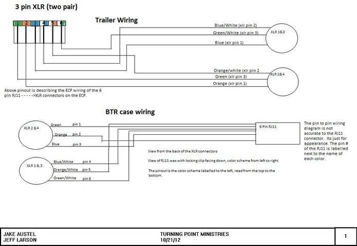
I am attempting to run our RTS 4 wire wireless intercom over two XLR connectors so that at venues where there are no available ethernet patch points, we can have our 4 wire system through 2 tie lines. I have the correct pinout and have gotten it to work successfully so far. However I have this tick sound that is repeating the same 8 tick pattern over and over again. There are 4 wires of intercom and 2 of data on the pinout for a RJ11 connector. I understand that there are multiple things that could be wrong, but that fact that it works with a dirty feed makes me stuck. I am trying to think where I went wrong and what could be causing the tick? wrong pinout........etc. any ideas. Attached is a drawing, please excuse the quality of the drawing.
Wireless Comm XLR-RJ11.jpg
 
Sounds like a digital clock issue. Most likely the cables being used are "noisy", ie perfectly fine for audio level frequencies but not so with digital. I doubt there is an easy fix.
 
Let's start by asking which model of RTS system this is?
Assuming we're talking about something like a BTR800...

So let's remember that a 4 wire system is just that - it only uses 4 wires...
2 balanced pairs, no grounds.

Only 4 contacts of the RJ connector are used - the centre 4.
Let's use the numbering of 1 to 6 for the contacts.
3&4 will be pair one, 2&5 will be pair two. 1&6 would be a third pair in telephone usages, we don't use it for intercom.

Let's take a look at the BTR800 manual [pdf]http://www.rtsintercoms.com/au/rts/file?i=97084&lg=eng
On page 26 we've got a pinout for the RJ11.
Pair 1 (centre) is the output of the base station, pair 2 is the input.

So if you wired things more like this:
RJ XLR pin
1 N/C
2 In 2
3 Out 2
4 Out 3
5 In 3
6 N/C

You'd probably see better results...
 
Thanks for the input. The Pinout that I have was probably wrong or I used the incorrect one. I was using a Pinout that used 1 and 6 for data transfer. I'll try without.


Sent from my iPad using Tapatalk HD
 
That would be the right pinout for a keypanel.
But since the wireless is "dumb" and can't tell the matrix what it wants to be sent, there's no data pair in use.

Incidently, if you did have a data pair to connect a keypanel, you'd achieve best results by commandeering a third tie line and sending the data pair down that...
Using the shields to send any sort of signal is asking for trouble...
 
Last edited:

Users who are viewing this thread

Back