Vintage Lighting Scrimmer Troubleshooting and Repair

Hi all,

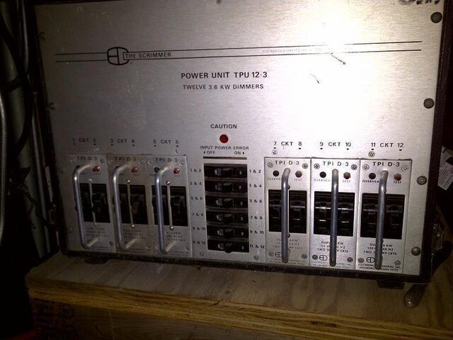
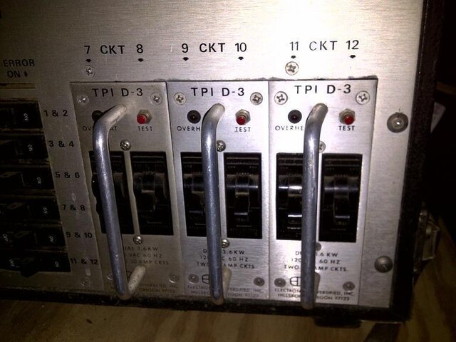
I'm wondering if anyone has any troubleshooting and/or repair information on this unit? It was working fine a week ago then 2 dimmers on the same cartridge went out. When that happened, I swapped it with another cartridge that was operating 2 other channels (swapping with a known good part for diagnosis). Since then, 1 more dimmer has failed. Shows begin in 3 weeks and I need all 12 channels of our system running.

I have no problems with servicing the unit myself, I'm perfectly capable of rewiring and soldering circuit boards should that need to be done.

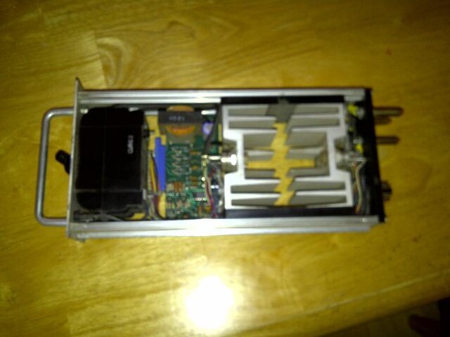
IMG-20101215-00042.jpgIMG-20101215-00043.jpgIMG-20110408-00181.jpg
 
I assume when you say "Out", you mean they are black as compared to full on.
Picture is out of focus on the board, but it looks like an old analog SCRimmer! (Know them well.) If both channels are out, look for a small fuse mounted on the PCB and make sure it is good. These also have an edge board connector. (blue in picture.) Unplug and re-seat. If that works, then clean the contacts on it.
These guys use back-to-back 63 amp SCRs, for a bridge capacity of 126 amps on a 3.6k dimmer. Each module only works on one phase and has one small transformer supplying power. In the US, the primary is 120v and the secondary is (from memory) 12 volts. There is one comparator used in the ramp generator that has two small trim pots near it. One pot controls low end set, the other sets your high end. If either are dirty, they may cut out and that would kill the ramp and give you a blackout condition on that module. Look carefully where they are set, then try moving them back and forth a few times, ending where you started.
If the transformer checks out, and you reseated the connector, and moved the trim pots around, and still have a dead module, then we need to get more advanced. Not sure about this board (blurry) but usually contains two dual comparator chips, or one quad. One little transistor, a regulator that looks like another transistor, and two opto-isolators (MO2010 ? At work, not sure.) Very rare for these parts to fail.
Post if you are still stuck.

Oh, I am assuming that you do not have an overheat light on and the "test" button isn't broken. I did have one of those thermal switches in the overheat circuit cut out once.
 
Last edited:
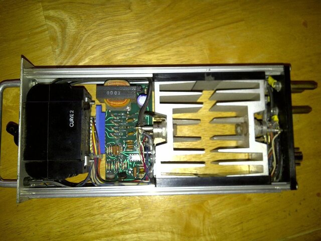
Sorry about the blury picture, here's a better one. You are correct, no overheat light is on. I will check what you recommended and report back. Thank you very much for your input.


IMG-20110408-00182.jpg
 
Yea, this one uses a quad comparator. (Basically, four op-amps in one chip) Very generic chip by-the-way. The two trim pots are at the bottom of the pic, somewhat to the left. I think the opto-isolators are obscured by the SCRs. Thermal cutout is the black plastic thing mounted to the heat sink. Here are some more layout notes:

1) Transformer is at top, with diode quad to the upper right. There is one more lone diode hiding up there to supply input to the ramp generator. Check for open primary or hidden fuse around transformer.

2) 8 diodes with some resistors and caps under it that interface the opto-isolators to the SCRs. (very reliable part of circuit, except maybe the resistors.)

3) Comparator IC, with clamping transistor about 1/2 inch down. Usually reliable.

4) Trim pots. big problem area, and most likely cause.

5) Eight pin "tube socket" type connector at back. Most likely (from memory) has six wires running to it. Two are the primary of the transformer, one frame ground, one circuit ground, and two control lines.

Don't hold me to it, but I think the transformer primary wires are actually black and white. Should have a DC resistance of something like 200 ohms (+1000% / - 50%, in other words ABOUT 200!)

Look for any visuals like a toasted resistor. More likely to be those stupid pots.

Somewhere back in my shed I actually hand wrote a schematic for this circuit, but that was 30 years ago!
 
If none of the above is successful, search Service and Repair Vendors for DimmerDotCom (he has this manual posted on his website), Lite-Trol, or Alan Child.

We used to have an EDI member, Tracyu, but with Cooper Controls closing the Oregon factory I'm not sure of his status.

EDIT: Tracy is no longer with Cooper Controls.
 
Last edited:
I got all but one unit (2 dimmers) working thanks to all your help. The last non-functional unit will work after resetting (off, then on) the right side breaker, but the lights only work for about 1 second then go out. The breaker is not being tripped, it just seems to appear to reset something inside the 2 dimmer unit. The overheat light is not coming on when this happens, but the overheat light does come on when I press the red test button, so I know the led overheat light is not burned out.

Any ideas?

Yea, if the LED lights when you push test then we know the DC supply and the transformer are fine. If both channels work for a second, then both channels stop working at the same time, but you can still get the LED to light when you hit test, then the problem may be the quad comparator, or the regulator. The regulator is a small transistor looking thing, but not the clamping transistor. It probably has 78L12 or 78L15 in the part number. (can't remember which one!)

Looks something like this - 78L12 TO-92 - $0.05 : OrzParts.com, : Online IC SuperMarket Ship to Worldwide,Great and Transparent price

If the zero voltage detector or trim pots were bad, you would not be able to get any load to light, so we know they are ok. It sounds like the regulator is turning off which may be caused by the regulator itself, or by excessive draw by the comparator chip. These regulators only can handle about 100ma, so hard to say if the comparator chip would even get a chance to get warm to the touch. If it is, then that is your smoking gun.

When a 78L type regulator goes into over-current protect mode, removing power and re-applying it will reset it. This sounds like what is happening. (Not to be confused with a dimmer over-current protection, this is just a control circuit)

The quad op-amp / comparator chip looks something like this - http://www.capsnsuch.com/index.php?route=product/product&product_id=112
but you will need to get the part number off of it and google it. It is fairly generic.
 
Last edited:
Thank you so much for taking the time to reply. I'll look at the two components for the numbers, order and replace them (they appear cheap enough, may as well just do both at the same time). I'll let you know if that worked.
 
Thank you so much for taking the time to reply. I'll look at the two components for the numbers, order and replace them (they appear cheap enough, may as well just do both at the same time). I'll let you know if that worked.

IMHO, this may not be the fastest or cheapest way to get your dimmer working. We call what you are doing "shotgun" troubleshooting--replace parts and hope it works. Without a proper extension harness to energize the dimmer outside the rack, a meter and/or oscilloscope, and a schematic in front of you--this may be a long and frustrating process. Oh, and you will also need a solder sucker to get the parts out without damaging the PCB.

I suggest that you get a quote from a reputable repair shop such as Lite-Trol.

Just my 2 cents.

ST


Thank you for your input, in my real profession, I would give the same advise to a similar line of questions. But, in this scenario, I feel this is a simple fix for me and makes 100% sense.

If this was anything more than a hobbyist project on vintage equipment, I would definetly be seeking a professional repair. The minor cost of parts to attempt a "shotgun repair" are vastly different than hiring one of a handful of people left in this world that actually know about this equipment. Having said that, If this <$5.00 repair does not work, I will likely be seeking one of them out.

Cool-please let us know the outcome!

Cheers

ST
 
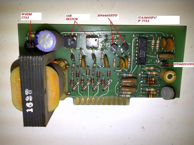
Well, I got a good look at it today, and see 3 transistors. Yes, they're transistors, looking at the numbers on them. I can not find the regulator that was mentioned unless it's the round part next/above to the transformer I don't recognized what that piece is. What do you think?

IMG-20110413-00189.jpg
 
Slightly different then the ones I have. The "W02M7711" is just a bridge rectifier. U1 and U2 are the opto-isolators. all the stuff below them are for SCR interface. Q1 and Q2 are drive transistors that buffer the output of U3 (the quad op-amp) and drive the opto-isolators. Q3 is the clamping transistor in the ramp circuit, which uses the cap directly above it to produce ramp timing. This circuit differs in that it uses a lone zener diode to achieve regulation by only regulating the max size of the ramp. In this case, I doubt the zener is the fault. Nothing on the board looks like it has any thermal damage. In fact, except for the odd looking trim pot (upper), the board looks very good!

Although the problem most likely is on this board, the edge connector allows us to do a quick "divide and conquer" to confirm this. Simply swap the whole board to another known good dimmer. The problem should change over to the other module. If it does not, then you may have a bad thermal sensor, or a problem in the wiring or sockets. I doubt it, but the test is free so why not try.

Now, back to the board. Since both channels go out at the same time we can eliminate any parts that are channel specific. This includes Q1, Q2, U1, U2 and all those little parts in the area below them. DC from the supply lights the test LED so we know the transformer and diode quad are good. Electrolytic caps (big blue thing in the upper left) sometimes dry out with age. That would disrupt almost everything. They are cheap, I would change it out anyway.

The problem you describe reeks of a ramp generation failure. In this case, the parts for ramp generation are all in the area of Q3. The 2N4401 is one of the most common transistors around, but I suspect it is not the problem. The capacitor directly above it is a more likely suspect. Some of those larger molded caps had problems. The guilt of U3 is less in this version of the circuit as it would most likely get quite hot if it failed.

The nice thing about this board is that with the exception of the transformer, every part is about as generic as it can get, and all are still available at very low cost. As Steve mentioned, there was an extender module that was used to service these units. With that tool and a scope, this is one of the easiest dimmers to service. However, without, its a bit of a hassle to keep plugging and changing parts by trial and error.
 
So I swapped control boards this evening with a known, working unit. The problem is still on the original piece, meaning that the issue is not on the control board.

Another thing I observed, after resetting the circuit breakers on those two channels and the lights going on, they stay on slightly longer if I leave them off for 5 minutes before resetting. If I reset them right after they go black, they go black again within a few seconds. One channel goes out before the other, not at the exact same time, 2-3 seconds between the two channels going out. Also, they occasionally flicker before going out completely. I have checked wiring connections several times and see no cause for intermitents. I am assuming that one or more SCR or the thermal sensor(s) is the cause. Would my assumption be correct as I don't see anything else left to be a possibility?
 
For all four SCRs to be bad would be highly unlikely. The good news is that this should be a simple fix. (should..) The flicker - then - out would be odd for SCRs as if one failed in the open mode, you would still be able to bring the light to 50% as the dimmer would still be putting out 1/2 wave power. If the thermal cutoff kicked, both channels would drop at the same time. Time to follow the power trail.

Start by moving the module to another slot. Does the problem move or does it stay with the same slot?

From the input tie block, power travels to the primary breakers at the front of the unit. (This was an option on SCRimmers, but your pack has them. From there it goes to the common prong socket for the module. That connector is basically a modified stage pin connector. Check to see all three pins on the module have enough of a gap to make good contact. On the module, it simply loops to the breakers and then to the SCR's and then to the output pins.

Breakers can go bad Check to see if the terminals are tight as well. There is also the chance that the power for the control circuit has a problem. Check the octal socket on the module to make sure the wires are actually soldered to the pins. (once found one that wasn't yet the pack worked fine for years.)
 
JD, if you were nearby, I'd by you dinner!

The problem follows the module, no matter what slot it's in. I swapped the circuit breakers with a known good unit and there has been no change. I have checked all connections and saw a partially burned wire that went from one breaker to the other, I replaced this wire, and still have the same problem. I bypassed the thermal cutouts (temporarily and under close supervision of course) and the problem still exists, I then bypassed the thermal cutouts in a closed loop, and the overheat lamp illuminates as it should.

The only thing left are one or more of the SCRs being out? I'm going to try swapping them one by one with my know good unit that has been pieced apart for this diagnosis.

Other than the frustration, I can't say I mind this problem too terribly much. I have learned a great deal about these units in a short amount of time.
 
Believe it or not, I am still not convinced it is a SCR! This has got me a bit curious, so I ventured back to my shed and yanked a mod out of one of the old SCRimmers back there. The SCR's have a 10 ohm gate bypass resistor (on the pcb), so all 4 would have to be bad to knock it out like that... However, (something I had not remembered) the control board gets its power via one of the two breakers at the front of the module. On the unit I just looked at, the power tie is at the rear heat sink off of one of the SCR washer tabs. It then goes to a small GMA type fuse mounted on the back bakelite plate and then forward to the transformer. The neutral return is through the 8 pin octal socket. Good or bad, change that fuse. Any interruption of power along that path will shut off both channels.

As you noticed, the thermal cutouts are normally open, and wired in parallel, so we can eliminate them. There is no type of over current shutdown other then the breakers. (They relied on the brutal size of the SCRs for the safety margin.) Also, those pin connectors on the back are designed to "float" so inspect the crimp connections that go to them to make sure there is not wire damage right at the pins. Let me know how you make out!
 
I feel really stupid. The problem is the control board. Somehow I must've swapped the bad and good units, or the side plate which must've confused me on which unit was which while I was testing.

At least I know where the problem is now. . . sorta :oops:
 

Users who are viewing this thread

Back