Without going into much detail on the
Wybron stuff, they do some things differently than other manufacturers. While the others have one
pin out configuration across all of their products,
Wybron has a couple different ones. The Forerunner
line, as already stated, uses the same configuration as other manufacturers with pin 1 carrying 0 Volts DC and pin 4 carrying 24 Volts DC. However, on their other lines, pin 1 is 24V DC and pin 4 is 0V DC. Which brings us to the issue. If you
plug a device into the wrong
power supply, you will very likely let out the magic
smoke. However, some devices, such as the Smart Color PRO, have built in protection that can keep the magic
smoke from being released. However, as some of you have found out first
hand, the original Smart Color does not have that protection.
Now with that being said, I'll move on to the cable.
Apollo has pretty specific 4-Pin Data Cable Specifications that we state in our Smart Color
manual, on
page 23 (
page 5 of the linked PDF) and quoted below.
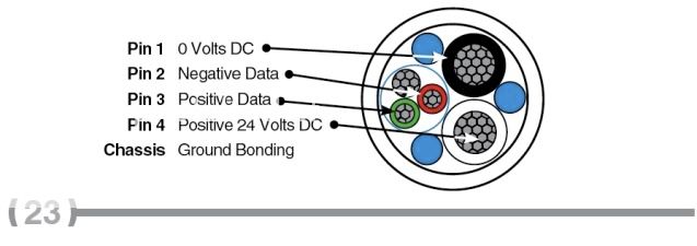
4-Pin Data Cable Specifications
Pin 1 - 0 Volts DC
Pin 2 - Negative Data
Pin 3 - Positive Data
Pin 4 - Positive 24 Volts DC
Chassis -
Ground Bonding
Physical Specifications
Conductor
• Data pair; 22
AWG tinned, annealed copper stranded 19/34
•
Power: 14
AWG bare, annealed copper stranded 41/30
Insulation
Data pair: color coded high density polyethylene, Red/Green
• Nominal Wall: 0.0095”
• Minimum Wall: 0.007”
Power: color coded,
PVC 80ºC, 300 volt black & white
• Nominal Wall: 0.015”
• Minimum Wall: 0.012”
Shield
Aluminum/
mylar around 22
AWG pair,
aluminum side in, 100% coverage
Drain
24
AWG tinned, annealed stranded 7/32
Jacket
• Black
PVC
• Nominal Wall: 0.035”
• Elongation: 100% minimum
• Tensile: 2,000 PSI minimum
O.D. Weight/m ft.
Nominal O.D.: 0.290” Weight: 60 lbs. per 1,000 ft.
Environmental Specifications
Operating Tempertures
Plus 80ºC, Minus 20ºC
Conductivity
15.5
Ohm (max.) per 1,000 ft. @ 25ºC
Impedence
Data pair: 60 Ohms calculated
Capacitance
• Data pair: 27 pf./ft. nom. cond. to cond.
• 51 pf./ft. nom
One thing that came to our attention very recently concerns the
shield. There seem to be a couple schools of thought on this. We state that the
shield should be connected to the chassis of the
connector at
both ends of the cable. However, others will only connect it at one end or not at all. The
shield is what you would think, a
shield. More specifically, a
shield from RF interference. It also serves the purpose of a
ground bond. Now this is where things get dicey. For it to work as an RF interference
shield, both ends need to be connected, which is why
Apollo states that. On the flip side, if your
power supply were to flake out and cause
voltage to stray to the common
ground, you would not want the
shield attached at both ends allowing your accessories to "go live" with the
power supply. Now, yes the
breaker* should trip, but if it didn't or someone happened to be touching an accessory, it could be bad.
*Remember,
power supplies should
NEVER be plugged into a dimmed source!
Now I'll move on to the
return line debate. This is something else that seems to differ between manufacturers.
Apollo recommends the use of a
return for two important reasons:
1) to maintain
line voltage and minimize
voltage drop along the length of the run and
2) to terminate the data signal (done in the circuitry of the
power supply).
We realise that this is not always possible, which is why we offer a
4-pin Data Terminator. As stated on that
page (
emphasis mine):
The
Apollo 4-pin data
terminator is a useful device to eliminate data
reflection in a
short-run 4-pin
system.
Total cable length from PSU to last accessory should not exceed 100 ft., or
voltage drop may result. Remember, a 4-pin cable connecting the last accessory to an
Apollo PSU will properly terminate the data signal. Without some type of data termination, poor
fixture performance may result.
Which brings me cable length/distance. I don't really understand the whole "
head-feet" thing, but I haven't ever really tried to either. So just to be sure things are
clear from my end, I'll
cover what
Apollo states. It has been brought to my attention that there is a little more confusion than I was even aware of. You'll notice in the quote above that the total cable length from
PSU to last accessory should not exceed 100 feet. However, from
page 5 of the Smart Color
manual (linked above):
Note: Total cable length per
circuit must not exceed 200 feet/60m.
The use of a 4-pin
return line must be used to minimize
voltage drop
and allow maximum performance. Route the 4-pin
return cable from
the last
scroller back to the
PSU 200W, 400W or 600W to maintain
line voltage across the
system, and to terminate the data signal.
There, the total cable length of 200 feet includes the
return line. So it still stands that the total cable length from
PSU to last accessory should not exceed 100 feet. If you are using one of the
Apollo 75W supplies that has no option for a
return, your total cable length can be 100 feet and I would suggest using one of the 4-pin Data Terminators. If using one of the other supplies, you are still limited to 100 feet from
PSU to last accessory because the
return line would put the total at 200 feet, the limit.
Now to be
clear about what I just said, that limit has to do with the
power, not the data. The data can go much, much further than that. The resistance of the cable with regards to the
power causes about a 2V DC loss in 100 feet. Couple that with the
momentary voltage drop that occurs when all the scrollers on a
line are given a command all at once, and you start to see random scrollers randomly resetting. The
return line greatly minimizes that.
Hopefully, that will help
clear some things up, but feel free to ask if there are more questions or I need to better clarify something.
Thanks