Old, Old lighting fixtures?

There no doubt was a photo of a ovalite with a description of the two major types. Welcome to the forum also, hopefully you will long be able to help others just as curious in time as you are now.

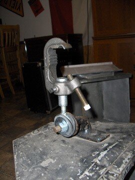
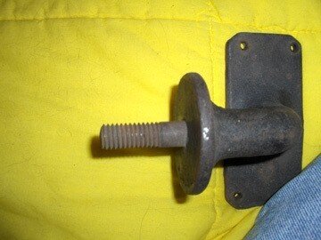
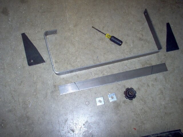
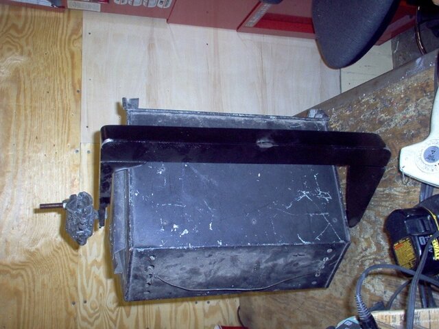
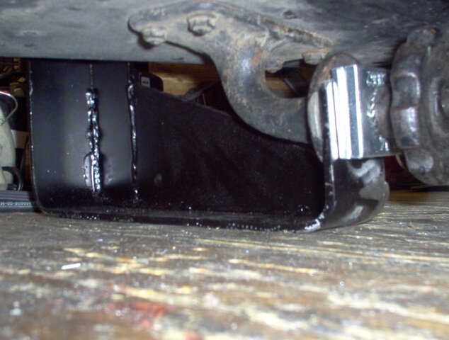
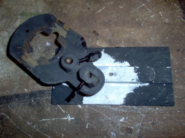
Urr. stop don't remove the cast stand yoke and replace it by drilling for a standard two sided yoke. Instead just use the one sided yoke - remember base up, and make up a clamp that will still hang but preserve the intregrety of this antique without destroying it.

One side just requires slightly more steel on that side as opposed to less on two sides to keep it in place as per the fixture design. To drill it out for a yoke, ... might as well put catchup on a hot dog or more realistically replace all Lekos for Par can's in easier to maintain and being a sin for those in the future who get what you screwed up.

Two bulb bases are either a screw up by way of someone before you, or a slightly different fixture that's within concept of what will have been useful but not a pure Ovallite as the fore runner to what is todays' scoop.

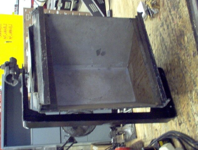
If in gel frames a question about having extra gel frames for this fixure... it's a 1900's invention, most likely not extra if even any gel frames for such fixures. Cut and rivet or weld up your own - simple enough and more cost effective. While doing so, if you intend to use this fixture, you need a safety screen for it which by todays standards would protect the talent against large chunks of hot glass should this lamp fail catestropically. Simple as another gel frame added to the fixture that has hardware cloth or at least chicken wire welded or encased within it sufficient to keep back any large chunks of glass should the bulb fail.


On the ground wire, that's for the most part acceptable to modify the antique gear in having, as with giving the piece a proper strain relief. Normal placement of the grounding wire would be bolting within say three inches of the lamp base or within a few inches of where it enters the fixture dependant upon the fixture and best place to put the ground. Often, the closer the better to where the conductors terminate. Thru bolting for a 10-32 screw with lock washers is the norm without so much going into my own ways of doing it.

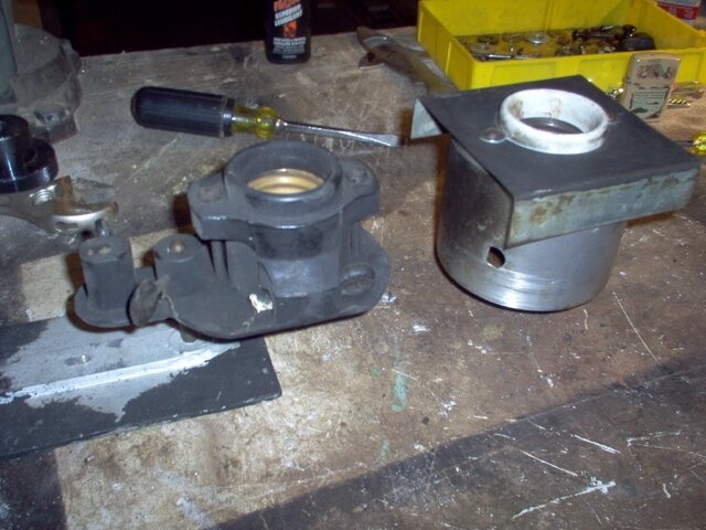
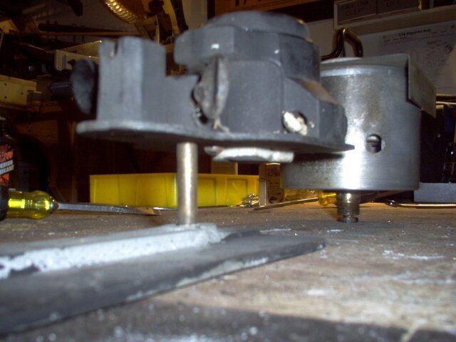
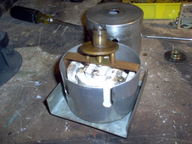
Have a look at your lamp base contacts also in if needed a replacement or cleaning and re-surfacing if needed.

If asking about a gel frame for the Kliegl fixtures, if 6" it's the normal 7.1/2" gel frames most fixtures or 6" in Leko or Fresnel or PAR 56 use. If on a 8" fixture, its' the same gel frame as a 8" Leko or Fresnel or PAR 64. There was a standardization of gel frame sizes in Lekos.

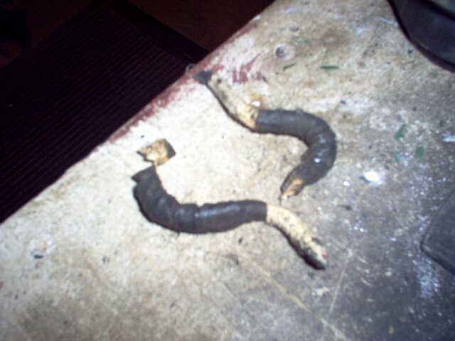
Best of luck and read much into the details of re-wiring, more to it than just adding new wires, or in disposal and removal of the asbestos than what's easy in doing it correctly.
 
Thanks for the info. I was wondering if I would have to fashion my own gel frames...I'll have to work on that. Wood would be the easiest for me since I don't really weld, but it's probably not a very safe idea either. Great suggestion on the hardware cloth too.

I had tried and failed to think of a way to clamp the light using the existing hardware. I'm just not quite sure how I can clamp to that little bolt on there and keep it secure. I'd be open to any suggestions; I really didn't want to drill holes either, I just thought it would be the only way. I tried coming up with some sort of system where I would use two metal washers and two rubber washers surrounding an eye bolt that fit into the c-clamp, and then you could tighten the bolt on the fixture hardware to keep it from moving around the eye bolt, but I can't seem to find hardware that fits; I'm thinking it's something like a 9/16" thread on there. Additionally, the only eye bolts that would fit the clamp had eyes that were waaaay too big. I guess I'm just at a loss for ideas. Help?

-Dan

P.S.: even though they're old and comparatively inefficient, I do love these old Kliegl instruments. My personal favorites are the fresnels though; they have a much more even light transmission than the modern altman's or others. Unfortunately, I do not have any of those fresnels yet...someday though.
 
"Somday though", yep another budding collector that apriciates what was done. Not always better but sometimes in often a less refined way of doing it, interesting unique qualities to what was done.

Just further inspeced my own Ovalite, that flowering knob is rusted solid to the bottom of the fixture mounted horn like shape to the bracket. Could be that it's 1/2-13 threads per inch or the more ancient 1/2-12 old English standard you still run across these days at times by way of China import. McMaster Carr I believe if not stocking such bolts can get them reasionably cheap. This given I have thrown out all 1/2-12 bolts and nuts hopefully I have gotten over the years in really throwing a wrench into the system.

Theoretically it's 1/2-13 in thread but 1/2-12 is a possibility to be aware of if a standard if 1/2-13 doesn't thread properly. Doubtful it's a 9/16 of what ever thread though possible and still exists even back than not used much.

Ok, let's solve the problems. First, most say 1Kw DKZ lamps you might use are universal burn meaning that in installing a modern lamp, it wont' matter what position the lamp is in - it will matter slightly what position the fixture is in by way of proper cooling however. If the case that it won't be on long, you can burn base down. Most other lamps down to 300w you might use are also either universal burn or burn base up so that also should not be a problem. Check the lamps if you got any with the fixtures for this noting on the upper part of the bulb should it be different.

What's said kind of concerns me about wiring skill, have what you do inspected by a qualified electrician or the staff of where you got the fixtures from. There are little details that need to be seen in making a safe fixture which cannot be conveyed. Yes... you can use lumber but it's not the best idea and the local home center should have sufficient if not oversized steel suitible to have welded up or to rivet. Most welding shops can knock out gel frames for you cheaply.

On the yoke bracket, if your's is like mine in having the bracket on the bottom, the old books show a steel bracket used for underhang. This would be safe enough as a bent piece of 1/4" x 2" mild steel bent to go between the bottom bracket and say a C-Clamp. This all given the above possibility of using the fixture upside down. The theater you got the fixtures from would no dubt be able to bend this plate for you sufficiently.

My fixture has a standoff between the stop point on the bracket and where the knob stops in threading. I would recommend a single or double Unistrut washer available from any home center in taking up the gap if not a piece of 1/2" plate that's drilled. The less washers and other things to fill in the gap, the more stable your mount.

Let's get into concept in how this yoke works. This of course given your as per question of the day question of mine question of what part it is, if missing like mine, that part that goes between the fixture and the stand is missing, it is a problem as with my fixtures. Otherwise, it would be easy to either stand mount the fixtures and or use that part to start what ever is needed in making it go hang.

As a concept, the cast bell of the fixture goes to a wide flat area which for all intensive purposes is a clutch cam. Rubber don't like heat but will work for a short amount of time. With a clutch cam as still used on most Mole Richardson type studio lighting fixtures and most all audience blinders of what ever brand, the wide surface area of this joint provides friction in preventing such a joint from moving once tight. Works well in fact, but often there is some kind of silicone or teflon or other fiber pad added so as to prevent friction while adjusting. Surface area is surface area in keeping the fixture from moving, a padding between surfaces doesn't overall prove detrement to this, although some heavier or more off balance fixtures such as this might not use one and instead use a kind of clutch/jaw method. Little teeth used to keep into position.

For this fixture, I might not add anything given the position of the single yoke. This might benefit by the friction more.

Added to the fixture, you need no doubt to also find a place to mount a safety cable.

Again good luck with the project and old fixtures you have under your caretaking at this point. First do no harm, than make them servicable. This followed by if you cannot afford to do it properly, don't do it as best you can in knowing better but making a temporary fix anyway. This also followed by if you don't know what you are doing you shouldn't be doing it, seek supervision. Most scary of all is not knowing better and having to learn by your mistakes. Had a multitude of my own over the years, it's hoped that others don't make the mistakes I have made in re-learning the same things, but on the other hand it's an eyes on the project type of thing and only so much one can help on-line.

No offense but a definate warning, this coming from the supervisor of a department that wires cable and fixtures for a living. Just had to fire one of my assistants this weekend and have to re-wire all of the cable she has made in the last month or two. Almost killed someone 30' up by way of what she numorously was taught how to do yet it would seem she still didn't get it. This with supervision and instruction. There is no learning curve, only proper supervision and instruction, than learning the trade or gone. What's theoretically safe only comes after instruction and experience. Shouldn't be a learning curve in doing stuff safely for what others risk their lives in what you learn with.

I urdge you to have what you attempt inspected if not get prior guidance in what you are doing before you attempt it. No offense but after some time such a concept will also be shared I'm sure.
 
Last edited:
Thanks for all the information! I did finally figure out a way to use the c-clamp with the existing hardware: I have a 5/8 flat washer, 5/8 rubber washer, 1/2 dia. 2" eye bolt, 5/8 rubber washer, 5/8 flat washer, and a metric sized nut sandwiched together on the existing threaded rod coming out horizontally. This provides me a vertical threaded piece (the eye bolt) to screw the c-clamp onto. The metric bolt seems to work fine, but it is just a tad loose, so I might look into some of the "older" bolt threadings you mentioned in 1/2" size. This sandwich configuration I came up with provides a nice friction fit which you can loosen and adjust to give the ability to move the instrument up or down (can't remember if this is referred to as pan or tilt). I think for a safety cable I will loop it through a couple of the vent holes on the top of the instrument, since there's no yoke for me to attach to. I will make sure and have the wiring checked, but the only real different thing I'm doing in this case is adding a ground, which from what I understand, should be bolted to the chassis somewhere near the lamp base. Correct me if I'm wrong here. Additionally, as I understand it, polarity on incandescent fixtures is not important so long as one wire is positive and one is negative. I have 16/3 SOOW cable to do the wiring, which may be a bit small, but I don't think that 14/3 would fit through the holes in the top, and the cable run will only be about 3 feet. I will check out welding places to see if they can punch a few frames for me; that would be ideal, but the TD at the theatre I got these from said that he has used luon (sic?) wood for gel frames with no problems before, so I may be able to do this.

One item of concern is heat dissipation. If I hang the light as I intend to (upside down) with a 405W PS40 lamp, the heat will of course rise to the top of the fixture, but it appears that all the heat venting area is at the bulb base, since it was intended to be used base up. I would like to be able to use these lights possibly for extended periods of time, so that's why the base down issue concerns me. I could try to mount them upside-down on the pipe, but I'd rather not, as that seems like a sort of precarious position, and since c-clamps are not really intended to work like that either. Can I get by using the instrument hung base down, or do I need to figure out a way to use it base up? As an additional note, I plan on using a hardware cloth screen and diffusion gel on this lamp, but I will maintain the inch or so gap between the edge of the reflector and the gel frame track to help some with heat.

I will try to post some pictures of all this stuff soon!

-Dan
 
Last edited:
Correct on the ground, incorrect on polarity and positive or negative. This is alternating current, there is no positive and negative only hot conductors and grounding conductors (the neutral.) Given this is a screw base lamp, there is a defianate polarity to this fixture. The hot (black) always goes to the center bottom contact on the screw base, the neutral always goes to the screw base shell. This way when un-screwing the lamp from the fixture, there is no chance that should your hand touch the screw base on the lamp you will get a shock.

16/3 SOOW cable while rated for the amperage is not rated for the temperature. Stamped on the cable you will see 90C, that’s the temperature rating of the wire. A 500w lamp will get much hotter than that. Your local or internet theater supplier will sell heat wire. This either as a multi-conductor cable such as a 14/3 200c wire or individual conductor heat wire such as SF-2 at 200c also where you would use a fiberglass sleeve on it just as if a modern Leko. They should also have in stock 3/8" NPT cord grip strain reliefs that would fit your hole possibly with drilling it out some. There are other options for strain relief and above types of thing but those are the most common ones.

Again, them minor details that come with experience, training and supervision. SOOW wire inside this fixture would be dangerous to use.

Luan Mahagony Plywood. Yes it would work as a gel frame - technically you are supposted to flame treat all exposed surfaces of it, better not to introduce lumber to a up to 1Kw rated lighting fixture. The second outer gel frame slide on the fixture would be a good place to mount the gel with the first for the hardware cloth - best in it’s own gel frame. This will help let the heat out and you tend to want some gap between the hardware cloth and the gel or the hardware cloth will burn thru your gel.

Very familiar with this 405w street light lamp, debatable about base up or base down in using the fixture given heat. Again back to the concept of the 1/4" x 2" mild steel that is bent to go into the fixture mount, than bent around the side of the frame and comes to the top with a ½" hole in it to mount a C-Clamp on. This would be sufficient to properly hang the fixture.

As opposed to all the concepts you have so far with Eye Bolts, just drill the strap for your bottom knob, perhaps add a Unistrut washer or two as a spacer and you now have the fixture mounted properly and sufficiently strong it will hang correctly. Think of a large C-Shape to the steel that bends around the fixture and comes to the top for your C-Clamp. Kind of a half yoke only it’s mounting to the fixture at the bottom and mounting to the clamp at the top. If worried that the 1/4"x2" piece of steel would be strong enough, a 5/16"x2" piece of steel will be just as easy to get bent to fit the fixture. Again your local welding shop or possibly the theater will be able to bend such steel easily.
 
I don't quite understand your proposition for making a yoke for this instrument. Are you suggesting that I take said mild steel, attach it to the existing fixture mount at the "proper" bottom of the instrument, wrap it around the back to the "top" side, and drill a hole in the top side to mount it to? or something else? Could you possibly make a diagram? Sorry I'm a bit thick in the head on this one...

-Dan
 
Yep, what you describe would be fine but I was thinking off to the side of the fixture instead of around the rear of the fixture for this bracket.

Starting at the bottom of the fixture - if your horn is like mine it is a right angle from the bottom of the fixture.

Look at it from the front of the fixture in side view of the bracket.

(The dots are your fixture. The dashes and I's are your bracket.)

------
. . . . I
. . . . I
. . . . I
. . . . I
. . . . I
------
I

(This is a half view of the fixture, consider the dots area double this width and mainly showing the shape of the bracket.

Your bracket from the bottom of the fixture is vertical and has a hole drilled it so it fits into the bracket. A bend say off to the left so it's horizontal and headed towards the side of the fixture. Another bend right so it goes vertical again once it clears the fixture. You are than headed towards the top of the fixture. Another bend right so you head horizontal at the top of the fixture and end in a hole for a C-Clamp once that hole is back at the center but now top of the fixture.
 
Last edited:
Whats the oldest fixture anyone has seen/used?

When I was on tour with the musical Chicago, decades ago, I got to operate the very, very old and original follow spots at the Shea's Theater in Buffalo (pre-renovation).

Made by Hall and Connolly, they were a lime green carbon arc, whose carbon rods were about 1/2" in diameter (as opposed to 1/4" for Super Troupers). These units were set up with positive rods feeding from the bottom on a diagonal (same as the carbon Strong Gladiators), with crank feeds to override the DC motors. I wouldn't be surprised if the entire unit was DC. The color frame assembly was a hand made wood box mounted on the front of the unit, with 6 rectangular wooden color frames that slid in to place via a string on a horizontal slider arrangement - similar to an Abacus. The iris and dowsers were wooden handled and the entire unit could be operated from either left side or right side. A great light !.

Next in line for cool early gear I got to use was the first generation of Strand-Century (US) computer lighting consoles - the Multi-Q and Micro-Q. This is the generation just prior to Light Pallette. The Multi-Q used 8" floppy disks.

We only recently stopped using our Strong carbon Super Troupers in 2001. They just got donated to a theater in Staten Island (NYC). Replaced with Lycian 3kw xenons. MUCH better unit, the Lycian !.

Still in use is the very first generation of Strand-Century double ended, quartz halogen ground rows. Originally configured for glass color media with 1" horizontal strips, in soldered together aluminum frames, that came in Red, Blue and Green. Very low profile. Eats color !.

Steve Bailey
Brooklyn College
 
ship-

I think I understand your bracket now. My only question is, if you're drilling a hole in the top that the bolt for the c-clamp will pass through, as well as the yoke, what is the point of the yoke? Extra support? Also, wouldn't drilling the hole destroy some of the historical value of the instrument? I'm not second guessing you at all, I'm just confused as usual. I'm assuming also that the hole would be drilled through the triangular piece that extends up from the top of the light to cover the vent holes, or would it need to go through both layers?

I finally have some pictures of the lights and my current rigging setup as well...I just have to put them on some web server so I can share them here.

-Dan
 
Here's some images. The first is of my current rigging setup; the second is the hardware that was attached to the instrument. I have a new question regarding that as well: this hardware has a lag to it, i.e. there is a segment that is not threaded. In order to make the yoke I would need to either put a spacer in here or find something that will fit in there to replace that piece, which so far I have not found. Any ideas?
-Dan
 

Attachments

  • HPIM0540resize.jpg
    HPIM0540resize.jpg
    28.4 KB · Views: 240
  • HPIM0536resize.jpg
    HPIM0536resize.jpg
    25.4 KB · Views: 219
I just had an idea.

Instead of drilling holes, why not make a sort of conventional yoke, upside-down?

Something like this:
--C--
I......I
I......I
I......I
I......I
I__|--

My diagram isn't quite as good, but essentially, you would have a square "O" around the instrument, where at the top where the C-clamp is connected, the two sides would overlap, and at the bottom where the yoke would connect to the older hardware, you would have a sort of dogleg, so at the bottom it would go horizontal, up, horizontal, and at the top there would be two overlapping sides that are held together through the C-clamp. With this setup, you're basically using the light as it would have been used in terms of attachment, and it gives the ability to adjust the light up or down some by loosening the nut at the bottom dogleg. This also eliminates the need to do any drilling. Thoughts?

-Dan
 
The C-Clamp mounted photo has the fixture up side down, that’s a problem if the fixture is on long.

Yep, exact same hardware. Gonna need to have that cast horn or a mounting flange run thru an oiled die of it’s proper size. Looks like the threading has had some wee age rusting.

Yes on your idea of a yoke proper wrapping both sides in you getting the idea. Now remove half that yoke - one leg of that yoke in the end that comes in behind the photo’d horn and you have where I was coming from in single leg yoke. Just a question of thicker steel in compensating for the double sided clamp. Same thing, just one leg to the yoke instead of two.

Absolutely no drilling of the fixture, get the horn/floor base mounting part back on and terminate your yoke in it. Over the weekend I’ll attempt to make and take photos of a bracket that would work.

“i.e. there is a segment that is not threaded.” Note above my concept of the usefulness of ½" Unistrut Washers that are 1/4" thick and 2" square. Kind of make nice spacers while keeping the surface area under the clamp wide.

Draw your bracket as it would be for a fixture in it’s normal position - vent’s up and base up. Note the shape of the mounting bracket below the fixture in your O’ shaped yoke having the horn of the cast mount getting in the way. Remove that leg of the O’ shape and you have what I drew out. One leg to the yoke, thicker steel to compensate for this.
 
Thanks for the reply again. I'm going to check into the steel for this soon; I'd need about an 8' section or so. I might actually see if I can get a machine shop to do it for a reasonable price, that way I don't have to mess with bending low gauge steel myself with a bench vise. I'm also going to try to get them to punch out some square gel frames too out of a folded sheet of aluminum. I was thinking of using a bunch of washers if I had to for spacers, but I ordered some 9/16"-12 hardware from mcmaster.com, and I'm going to see if those fit the threads. I really think it's 9/16"; from what I understand that was sort of an old standard for a while.

-Dan
 
SIU Carbondale still uses instruments from the 1920s. They had the lighting system remodeled about 5 years ago and received some new Source4 from the rigging company as compensation for a couple of botched line-sets. Lets see this is 2007 and they finally got some color scrollers, but still no automated lights.
 
Over the weekend I made the yoke out of 1/4x2" mild steel for my own Ovalite. Seriously mis-estimated the strength of this size plate verses the weight of the fixture. Attached is the photos of the upgraded yoke I had welded up for me today.

Should have made it at least 2" taller in yoke size as I had to cut away some at the corner angle irons in order for it to fit.

Still is the photos of what a 1/4" plate yoke once made more into a "L" channel single sided yoke would look like. Other options would be to use 1/4" leg thick by 2" "L" steel welded and or perhaps 1x1 or better yet 1.1/2" box steel of 14ga to make the yoke. Don't even think that 5/16" x 2" steel would be thick enough in the above recommendation - needs more support three dimensionally. The yoke in the photos about doubled the weight of the fixture but while there is bounce it's not going any where. Also found an old odd half cheseborough that seemed appropriate to hange this fixture from. This way if I really wanted to rooster the fixture out some I could.
 

Attachments

  • ovalite yoke a.JPG
    ovalite yoke a.JPG
    183.5 KB · Views: 227
  • ovalite yoke b.JPG
    ovalite yoke b.JPG
    192.7 KB · Views: 237
  • ovalite yoke c.JPG
    ovalite yoke c.JPG
    154.1 KB · Views: 251
  • ovalite yoke d.JPG
    ovalite yoke d.JPG
    192.8 KB · Views: 249
That's a nice yoke ship. It's making me wish I learned how to weld this year though. I almost did, but I didn't have time to actually do any real practice. I think I'll contact a local machine shop sometime soon about making these yokes. I assume you wouldn't mind if I copied your design?

-Dan
 
So I expect your fixture is for the most part very similar?

Just make them 2" taller in that this one with it's origional plates didn't clear very well the fixture.

Note the two 1/2" Unistrut Washers and 1/2" external tooth or possibly M-12 external tooth lock washer used as spacers between yoke and knob. The lock washer is very important and for all intensive purposes locking the fixture in place.

In tapping this and a similar stand mount box light over the weekend I found as I assumed them both to be 1/2-13 in thread, just hand tapped in not really being as refined as a modern bolt, add to this rust in changing the shape a bit. I also found that there was a steel bolt cast into the aluminum horn as it were cast mouting bracket. Keep aware that it's a steel bolt that is in an aluminum cast bracket when you go to re-tap your bolt and oil it up. I had a chip of aluminum come flying off in tapping mine.

Neither bolt was exotic in other than 1/2-13, it's just a cast or hand tapped bolt that is a little less refined but will re-thread properly. Want to use oil and tap also the knob.


Also in something that I had to cut and re-drill, make sure that your clamp hole is on-center with that of where your yoke will mount to the fixture. Mine was like an inch off on the first attempt at roughing it and it mattered a lot.

1/4 x 4 plate either be it welded up flat plate or 2" angle iron that thick. Either should work once the corners are reinforced. Otherwise as said, 14ga box steel especially if 1x1.1/2" should also work and even potentially be lighter. Show the photos, the welders should be able to structure it.
 
Last edited:
So it’s the turn to work on the Chicago Stage Lighting fixture. The Major PC fixture is for the most part done, just have to re-tap the 1/2-13 knob I bought for the bottom for 3/8-18 NPT and eventually clean it’s lamp base & wire it.

Found some interesting things about the Chicago fixture which is even more curious yet than the many pages of notes on the Major one I’ll spare you all from. Interesting also in that this fixture Chicago brand quite likely in absence of company history on either part might have been the fore runner to Major. As the photos show, while different fixture, the exact same lamp base, one without Major brand stamp in coming with the Mazda lamp, the other with “Major” stamped on the base and a GE non-Mazda lamp. Neither base was rated for the 2Kw lamp installed in the latter fixture. The Chicago fixture by the way did have a matt aluminum casting that was not painted. Under the handle it was not painted

Both fixtures had a mixture of square nuts and hex nuts in use, the hex nuts in both cases were no doubt replacements for what got lot amongst other often major lost parts.

Kind of thinking that the Chicago fixture dates back to the 1920's thru 1930's, the Major fixture from the late 1940's thru the 1950's (due to the square nuts.) The Major fixture while using the same lamp base (no longer available,) only allowed the lamp adjusted up and down and has no mounting for a reflector. On the other hand you don’t have to reach your hand inside of the fixture to adjust the focus. The earlier PC fixture has lamp base that is also fully adjustable up and down and even more so in compensating for say a 1Kw, 1,5Kw and 2Kw lamp. This in addition to micro focusing of the actual LCL within differences between lamps. It would seem that the primary reason for being able to adjust lamp height was less by way of micro adjusting for manufacturer defects, and perhaps more to adjust for different LCL’s of different wattage lamps.

The (later generation) Major fixture adjusts up and down, the Chicago fixture as if an old chemistry set magnifying glass adjusts up down and left or right on the lamp base by way of screw knob on 1/4" rod mounts. In addition to this and in a similar way to how really old microscopes work, this one has a mount for a missing reflector which works in the same way by way of thumb screw on a 1/4" rod. Really cool chemistry set type mounting to the fixture which lets you kind of universal adjust it both for lamp base and theoretically in the reflector. Only problem is that you have to have your hand inside the fixture while it’s operating to adjust. Safe enough as long as you are wearing asbestos gloves no doubt. Also to change the lamp, you would have to remove the reflector. No other way about it short of removing the lens which is held in the same way as a Fresnel with a ring.

Still two totally different fixtures, this one has three sliding light blockers below the lamp base to adjust for the wide focus while blocking the light, the Major fixture only has two. A normal Fresnel only has one of these plates. This is explained by a 9.1/2" slide focus range on the Chicago fixture in needing three plates to block the light, the Major fixture having 6.1/2" and a Fresnel not having near that range in slide focus a 3" at best adjustment in needing plates to cover up light spill. Front and rear castings are for the most part the same except on the Chicago fixture, the rear axis housing door uses a brass store bought #9R1174 sprig cup board latch - $0.08 each $0.85/dozen out of the 1902 Sears Catalog, the Major fixture uses a flip handle with latch. Fascinating as always when one can find the parts that make up not just a modern fixture say out of McMaster Carr, but especially on ancient fixtures where it’s in a similar 1902 catalog. (The ?1969 [MCMLXIX] Bounty Books, New York, 1902 Sears reproduction catalog is a masterwork for all designers and tech people tremendously useful for period pieces.)

Anyway, that’s the fixture in general I’m currently working on. The Ovalite is next up, all the box spots I so far have are done in at least de-rusting and wiring. The box spots at some point will become low voltage 60 degree MR-16 fixtures, the PC fixtures and wash light will stay the same. Some question of the age of the Ovalite I won’t yet be able to answer. Given it lacks a white or any paint in the reflector area, it possibly had a reflector assembly that’s missing which would make it a younger fixture. Than again, if no mounts for such a supplemental reflector are found, perhaps this fixture without paint pre-dates paint which would make it a really really old fixture indeed. Six more box spots to collect up from the theater that are currently mis-placed and I’m really hoping that I’ll find some missing stand mounts and lamp base assemblies, this much less more gel frames and lenses that are not that hard to replace but cheaper to find instead of buy. Missing a lamp base assembly also for the second oldest of them.

Love these old lights, on the upgrade to MR-16 lamp, I’ll of course first do no harm, than in doing so make them serviceable and a new life. For the others, and some of the box spots, I’ll leave original sans the wiring, just museum them by way of preventing them from further rust damage but not modifying them. Once done with these, I have a line on more ancient fixtures I will go about acquiring and studying. I find them fascinating.

Even by way of the Chicago fixture, it has soldered connections of wire to lamp base and the asbestos wiring is seemingly a 1960's/1970's style of it by way of external braiding to it. That and the friction tape about the bend to the wire is confusing. Solder connections while still done at times in th 1980's is normally a factory type of thing which puts this as origional asbestos wire. Yet this wire now removed seemed as if a later generation. Could be it was changed or that this braided asbestos dates to a much earlier date than I thought. Also the friction tape added to it. Never seen friction tape inside a lighting fixture before. While such tape was only electrical tape of the turn of the century thru like 1940's, it has been a main stay for certain applications since than = often in the 1960's thru 1980's used for bulking up cable to strain relief them. Perhaps it’s possible that someone that was experienced enough to re-wire the fixture by way of solder also wired it by way of friction tape at it’s bend to further insulate it. Heck, at some point even I attempted to use the magical friction tape within a fixture - this until it started a smolder fire while fresh. Expect this tech person knew just enough technique in doing good work to be dangerous in not understanding the full concept of their work. Certainly if further reinforcement of this bend in the asbestos wire were needed, fiberglass electrical tape will have been invented by than. This will have been the preferred product to insulate with. So end result by way of a sort of archaeology project, someone in say the 1960's thru early 1980's had re-wired this fixture to the best of their ability. They also replaced certain missing items such as the focus knob and some missing nuts. Focus knobs often seemingly missing it would seem in something not often found.

The rest of the fixture is seemingly in really great condition - at least once I scrape lots of applied paint off what will not have been painted. Amazing that this fixture with a 1K lamp survived years of flat black stage paint and the friction tape without a problem. Beyond this and especially the focus mechanisms for the fixture. Will have loved to see the reflector assembly but given what I have, it is enough to work with in learning lots on how it was once done and being fascinated.

Found some hammertone black spray paint at the store tonight. Should help a lot in touchup work on this fixture. In the mean time, it’s all about re-tapping holes and preserving metals from further detrition. Only one screw was rusted solid or corroded into the hole, that’s a good thing in also saving original fasteners.

Below photo 1&2 is the Chicago lamp base assembly verses the Major lamp base assemlies. Photo 3 the inside adjustment mechanism for the Major assembly. Photo 3 the reinforced with friction tape, asbestos whip inside the lamp base assembly that did a tight 180 degree turn. Photo #4 clearly shows this lamp base plus in it's rear the two completely seperate mountings for both lamp base and reflector assemblies witin one cast brass mounting slide mechanism for them. The rest of the photos are of the Chicago fixture excet photo 6 which shows the two exact same lamp bases fixture to fixture and their mechanisms for asjustment or mounting. One has Major, the othe does not. Don't mind the black paint, it's paint brush applied and after market. Final photo, a field stripped Chicago Stage Lighting PC fixture.
 

Attachments

  • 1-07 photos 019.jpg
    1-07 photos 019.jpg
    174.1 KB · Views: 198
  • 1-07 photos 020.jpg
    1-07 photos 020.jpg
    117.7 KB · Views: 198
  • 1-07 photos 021.jpg
    1-07 photos 021.jpg
    150.4 KB · Views: 183
  • 1-07 photos 022.jpg
    1-07 photos 022.jpg
    141.7 KB · Views: 195
  • 1-07 photos 023.jpg
    1-07 photos 023.jpg
    146.5 KB · Views: 196
  • 1-07 photos 024.jpg
    1-07 photos 024.jpg
    183.5 KB · Views: 184
  • 1-07 photos 025.jpg
    1-07 photos 025.jpg
    150.4 KB · Views: 201
  • 1-07 photos 026.jpg
    1-07 photos 026.jpg
    197.4 KB · Views: 213
Last edited:

Users who are viewing this thread

Back