Control/Dimming Electro Controls Dimmers / Panel

MillMA

Member
I have an Electro Controls Dimmer / Panel Model 720W5E at my school here that I have some questions about.

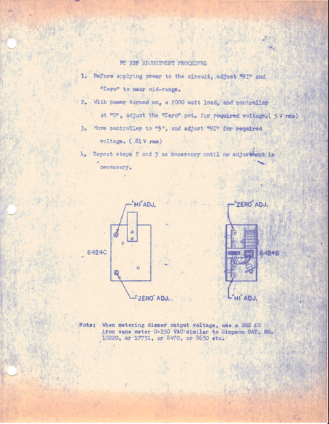
First, does anyone know what sort of control signal the dimmer modules (Model PC 22F, they look like SCR dimmers) take? I'm thinking of building an interface to at least MIDI (easy to work with) or, better yet, DMX for the board.
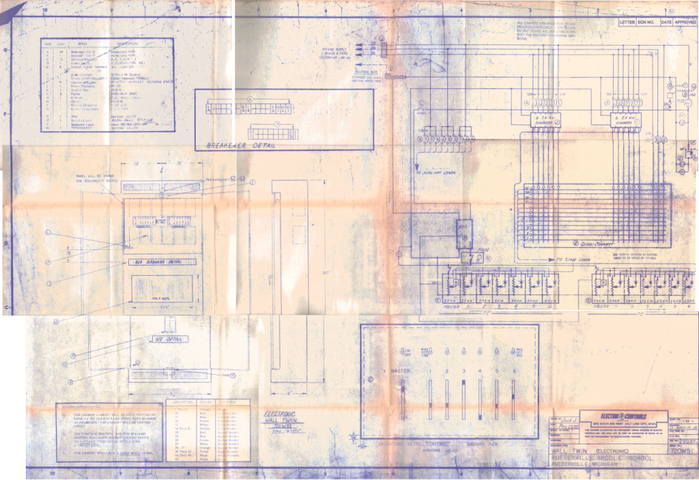
I was able to find a folder with the panel schematics and a short introduction to the board (I've attached the most info I have on the dimmers themselves, sorry for the blurry cell phone pictures, I'll try and get my camera in later) and it looks like it's an analog voltage based input, but I'm not sure (I could hook up an oscilloscope, but I don't want to fry a good DSO).

Unfortunately, I'm working on a zero budget through all this (my own resources limit me to about $100 - $150 total cost), unless it's necessary building repair (sinking fund).
Is it even possible?

Also, 4 of the dimmers don't work at all, and I noticed they're all on the same phase (the panel is 3 phase, wired directly from the building's switchgear in the boiler room, the breaker there is 100A fused). I checked the phase at the dimmer panel and I'm getting some odd results (all from a true-RMS digital multimeter):
- 120v from phase 1 to neutral
- floating from phase 2 to neutral
- 120v from phase 3 to neutral
- ~213v between phase 1 and 3
- 120v between phase 2 and either 1 or 3?
Also, my meter has a non-contact voltage feature (audible) and it sounds like phase 1 and 3 are live, but nothing from phase 2..
what would cause this? is it even fixable? (obviously by a licensed electrician, I'm just curious)
Could the dimmers be broken? (I hope not.. working with only 6 dimmers is a pain)

Just for background. The "stage" (cafeteria + elevated stage) was built in 1973. All the fixtures, raceway, and dimmers are Electro Controls. there's only 30 or so circuits, all the fixtures are par cans, Fresnels, or scoops. The control panel is just sliders and a group master, single scene, so it's kind of restricting as is.
I'd hate to think it, but I'm guessing each whip is asbestos insulated... I've already called the factory representative, who denies ever carrying Electro Controls (too long ago). so I'm pretty much out of directions here...

Any help (or random information for that matter) is appreciated.
 

Attachments

  • EC_WT701_DOCS8_SMALL.png
    EC_WT701_DOCS8_SMALL.png
    534.2 KB · Views: 545
  • IMAGE_119[1].jpg
    IMAGE_119[1].jpg
    105.3 KB · Views: 593
  • IMAGE_122[1].jpg
    IMAGE_122[1].jpg
    119.1 KB · Views: 1,003
  • EC_WT720_BPFULL_SMALL.png
    EC_WT720_BPFULL_SMALL.png
    957 KB · Views: 635
I can't comment on the EC panel other than to say that I've used one and about two years after meeting it had the pleasure of tearing the entire system out and replacing it with an ETC Unison rack -- but working in education, I have real concerns about high school students opening up electrical panels and digging around in them. Nobody wants to see a student get barbecued or lose their arm (or life) to an arc flash.

By the way, you may want to let your school district know that they're bound to get sued for ripping off the Minnesota Vikings' logo.
 
It is indeed an analog system, using a 0-10v control voltage. I assume your sliders are on the face of the panel that is open, or do you have an actual board. The sliders on the bottom are the patch panel. You slide the circuit number up until it engages the dimmer number. The dimmers use either SCRs or Triacs, EC used both types.
For whatever reason it sounds like you have a dead leg on two, probably a blown fuse in the boiler room. You said it read as floating, explain please. You need to get the school electrician in to figure that out.
You can not switch it to DMX without a converter and a board that is going to send the signal. Take a picture of the actual dimmer board.
 
EDIT:
yes, the sliders are on the other side of the open panel, It's actually a pretty simple circuit board, that's what I was hoping it would be. I'd almost like to try and build the converter board myself. (I'd throw in *good* opto-isolators obviously). would a PWM'd averaged voltage do it?
By "floating" it read the same as touching the two leads of the meter together: no potential read.
I've attached a picture of the front panel and circuit board for it.
/EDIT

Sorry, I do understand the risks and issues with 3 phase power..There's something to be said when that panel has one of the largest breakers in the building (still comparatively small to really large equipment at 100A, but enough to be dangerous)
I do know much better now, the data is from about a year ago. Right now, I have absolutely *no* aspirations of even getting close to that panel while it's not properly locked out upstream. (Quite honestly, I'm still a little nervous when the doors are even closed)
To show how much this system has been through: the last people to do significant work on the system (more than 10 years ago) thought enough to run 4 Fresnels on 20+ ft of orange extension cord out in the room (I don't think that's up to code). Then, sometime after that, 13 of the circuits were pulled out, the wire was still in the panel right before it went to conduit in the floor.
I don't mind the 3.3 - 15vdc with micro controllers and all that, <500mA max, and it would be really nice to have something more modern, but I agree that 120vac and up is definitely not safe yet. I was more thinking later on...
Still: is it possible to update without total replacement.

(as an aside: is the proper term "panel" as it's both the dimmers, quick connect board, and console in one unit)

I also sort of wanted to know if it's a major problem that could damage the equipment, or worse, cause a fire / major failure. (a simple yes or no is great, I can understand the rules against "how-to" posts)
(Our school is kinda too small and facing hard times financially to afford much that isn't strictly necessary either.)

/* off topic reply */
I wondered the same thing about our logo, and those of many other districts, awhile ago. Perhaps it's because we're such a small district? I guess It's still not an excuse...
/* end off topic */

I'd really like to get involved and learn this kind of stuff, but I'm still a group of one, if you will, at my school. Thanks for all the help.
 

Attachments

  • IMAGE_127[1].jpg
    IMAGE_127[1].jpg
    77.2 KB · Views: 417
  • IMAGE_124[1].jpg
    IMAGE_124[1].jpg
    117.1 KB · Views: 512
  • IMAGE_122[1].jpg
    IMAGE_122[1].jpg
    119.1 KB · Views: 384
Last edited:
Do you have a department head willing to write off for grants?

When I was in high school, the drama dept. head managed to get a $15k grant to build an outdoor stage. He actually got the grant before the school district even knew anything about his idea to build a stage.
 
There really isn't anything you can do to modernize the system without a new board and a DMX to analog converter to talk to the actual dimmers. The concern with a student going into a three phase panel is touching a hot leg incorrectly or creating an arc flash. If you have never seen a flash, go o Youtube and search for arc flash, it is an eye opener.
Do you have any dimmers that are on all the time? If so then you have a SCR or triac problem. If they don't work at all then it is something else. On the bottom of your slide patch you should have a line at the bottom marked AM. This is a test circuit. You should be able to check any circuit that has a light plugged into it to see if that circuit works. Also each circuit should have it's own breaker.
 
I worked at a school years ago that had an old system like yours. Our local theater install company rented them a console for a play. There temporary setup in order to link a board up looked like a science fair project. They had several converters linked together in order to make it work. I did not look at it too carefully but it was definitely some creative wiring.
 
Ok, I think you mean something like the "Non-Dim 3" circuit that has an ammeter in line right? Each dimmer has a breaker (according to the schematic) at 20A. The circuits themselves are not fused. Or, do you mean the Edison plug at the bottom left of the panel? There's no "AM" as I recall...

(any of the "broken" dimmers are dark, it's not like the SCR has broken down and/or has latched on somehow)
 
The problem the poster has is he would like to upgrade but he doesn't seem to have a board capable of outputing DMX. Without that the science project can't happen. Actually the conversion is actually fairly straightforward but in a temp system like what you used would look ugly. It requires a series of wires between the terminals on the converter and the analog dimmers.
 
I have recently worked on several EC dimmers of the same type, and they are not 0-10. They are in fact 0-15 volts dc control. Northlight DMX makes a DMX to analog circuit board that can be ordered at 0-15. Their 8 channel is something like $95. They also have a 24 channel at around $175. It would require somebody with good electronic skills to package it.

Oh and yes, I am in fact a theatre Master Electrician and also a licensed Master Electrician of the other sort.

As this is a school, it should have all of the appropriate approvals and be done by the school electrician or one that they approve.

Tom Johnson
 
Thanks for the 0-15v correction. I have used EC quite a bit over the years, we even have a couple still in use. I have never seen an EC patch panel that didn't have an AM test location. It is different than the nondims, the AM is for testing, the nondim is for supplying straight power for a motor or something that didn't need a dimmer.
The end result is the converter, as suggested, will do the job at a good price, but you still need a means of outputting and controlling the DMX.

I had assumed that the older EC dimmers were 0-10 as were most at that time. I used some old EC plug in modules to build a houselight dimmer for our theatre. I used a 0-10 converter and it has worked very successfully for over 6 years. Then just a couple of months ago the local college asked me to do some work for them. They had recently replaced their old EC system with ETC sensors. The house lights remained on an old EC dimmer system. They asked me if I could make them operate off of DMX. During my initial tests, I noticed that the modules were getting 15 volts at full. I then did quite a bit of online searches and found that it was 0-15 control. I went back and found the original schematics for our old system, and confirmed that the 15 was correct. Upon checking the Northlight site, I noticed that the analog converter can be ordered 15 instead of 10 volt. This made me wonder how much brighter our house lights would be with the additional 5 volts of control. After demonstrating the difference to the management, the decision was to leave it with the 0-10 control as it was plenty bright and the lamps were lasting a lot longer. Our houselight fixtures, as with many theatres are horrible to change lamps. As for the college, we are going to go with a Northlight converter wired for 0-15.

Just as a curiosity, about 18 years ago, I was working on a lighting system at a high school in Virginia. It was installed in 1972 and was a Luxtrol system put together by Bud out of Chicago. It was analog control of 0 to a minus 24 volts DC. Was that a lot of fun to convert over to DMX control.

Tom Johnson
 
Check my profile for pictures of a these type of dimmers that I retrofit now and then. Yes, they are 0-15VDC control. I would not mess around with this rack if you do not know what you are doing. The heat sinks on these type of dimmers float at 120vac!
 
As has been mentioned your 2nd leg has been dropped somewhere along the line, either the fuse blew, or something is open in the circuit. It has also been mentioned that arc-flash is a real issue dealing with 230+V systems especially at 100A. I ONLY use a Fluke above 120V, it uses filled fuses that prevent arc-flash. It is also rated to 1000V-ground.

There is nothing sadder than seeing a young person such as ourselves hurt themselves because they where poking around in live equipment.

Use the 1 hand behind your back at all times rule if you do keep working on this, it will at the least lower the risk of getting 230V across the chest.
 
Two of the HS theatres that still use EC systems are in the process of upgrading to Ions and S4 instruments. Not only are they currently using EC boards they are using EC instruments.
 

Users who are viewing this thread

Back