Control/Dimming Leprecon 612

DCATTechie

Active Member
I was sent these picture of a Leprecon 612 the other day by a friend who was asking how a lighting board works and what all the components inside do. And I told him......I have absolutely no idea, but I bet I know a few people who do. So I was wondering if someone could drop these pics into MS Paint or an equivalent program and make a diagram labeling the parts and describing what they do. Please ask if you need more pics and I'll see if I can get him to send them to me. Could we possibly also make this a collaborative article for mine and others future reference?

proxy.php


proxy.php


proxy.php


proxy.php


proxy.php


proxy.php


proxy.php
 
Start by looking at http://www.leprecon.com/productfiles/600blockdiagram.pdf. This is the block diagram for this board. It shows at a high level how it works. The detailed schematic is at http://www.leprecon.com/productfiles/301525C612mainschematic.pdf.

There's a processor (the large square chip) that runs a program stored in the eprom (the one with the sticker on it). This program gets its inputs from the various buttons (via some shift registers to reduce the number of pins needed on the processor) and from the sliders (via analog muxes so the processor is really only readong one at a time). Outputs from the processor go to a number of places, mainly thru some more shift registers used to add I/O pins - the LED display and status LEDs, the fader LEDs (via a DAC and some opamps to let them fade), and the analog outputs to the dimmer packs (via some opamps to boost the 5V dac output to 0-10v). There's a TTL-RS485 converter chip to generate the DMX.

The big blue cap and the chip with the heatsink are the 5V power supply.

/mike
 
The EPROM is a memory chip that contains the program that runs on the board. This program reads all of the inputs (buttons, faders) and generates the outputs (LEDs, DMX, analog/AMX). It does this one at a time, but repeats itself fast enough so it seems to handle everything at once.

A shift register is a serial/parallel converter. There are two types on this board, one (used for the switches) looks at 8 switches at once, on 8 pins, and lets the processor look at them one at a time on two pins. The other type lets the processor control 8 outputs in parallel (the LED display, for example) by using only two pins. These are both used because the processor doesn't have enough pins on it to handle all of this at once.

A mux (multiplexer) is a is a 1-of-n switch. In this case, it lets the processor, which has only one input that can measure an analog voltage, scan all of the faders in turn, measuring the voltage on each to determine its position.

A DAC (digital to analog converter) takes a digital number (such as 127) and converts it to a voltage (in this case, 127 would be 2.5V) to send to the dimmers. Another DAC drives the fader LEDs on the console to give an indication of brightness. The opamp is an amplifier, in this case used to convert the DAC output (between 0 and 5 volts) to the 0 to 10 volt levels that external analog dimmer packs need.

/mike
 
I have been tasked with trying to repair a couple of old Leprecon 612 consoles that were donated to us. One of them seemed to have unresponsive controls that I was able to fix by simply reading the manual and erasing the non-volatile memory. The other one wasn't so easy. The other one shows all channels full on (LEDs at the top of the console full on) but there is no control of the DMX stream (testing with known working dimmer pack).

My first thought was that the Analog to Digital Converter (ADC) was not working and that is why the console thinks all the controls are full on. But looking at the board I can only see one Digital to Analog Converter (DAC0808) and can't seem to find anything like an ADC. I have experience with microcontrollers and digital electronics, which is why I was tasked with these repairs. But short of reverse engineering this lighting console I have no other means of troubleshooting the board at a component level.

Earlier in this thread, n1st mentioned a block diagram and schematic, but when I try the links it just brings me to the Leprecon support page on their website. Seems like they don't provide this information anymore.
So, I was hoping that someone might be able to help me get a hold of those pages (schematic and block diagram) for the Leprecon 612 console.

Any help at all would be appreciated.
12400BA6-2DBD-43D9-BEEB-396395F259C6.png


Open the Schematic from a computer to see multiple pages.
https://web.archive.org/web/2013081....com/productfiles/301525C612mainschematic.pdf
 
I just wanted to provide everyone with an update: The block diagram and schematic are spot on. From the 
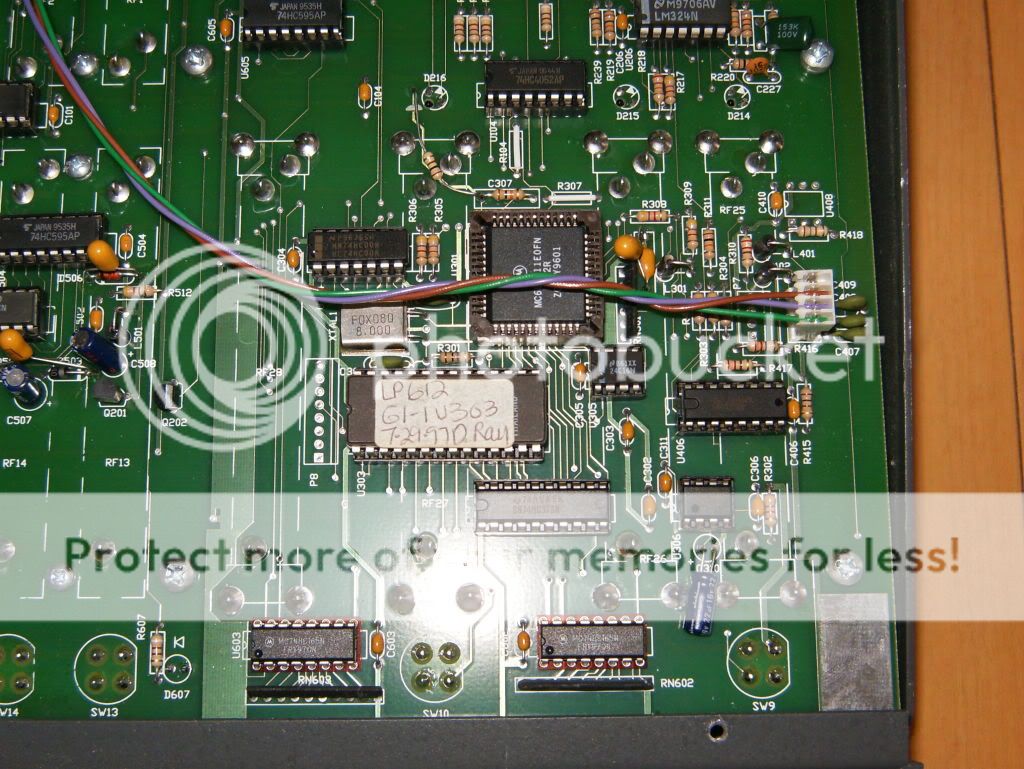
block diagram I found out that the ADC is in the main processor U301 ( 68HC11E0 ) and all the 
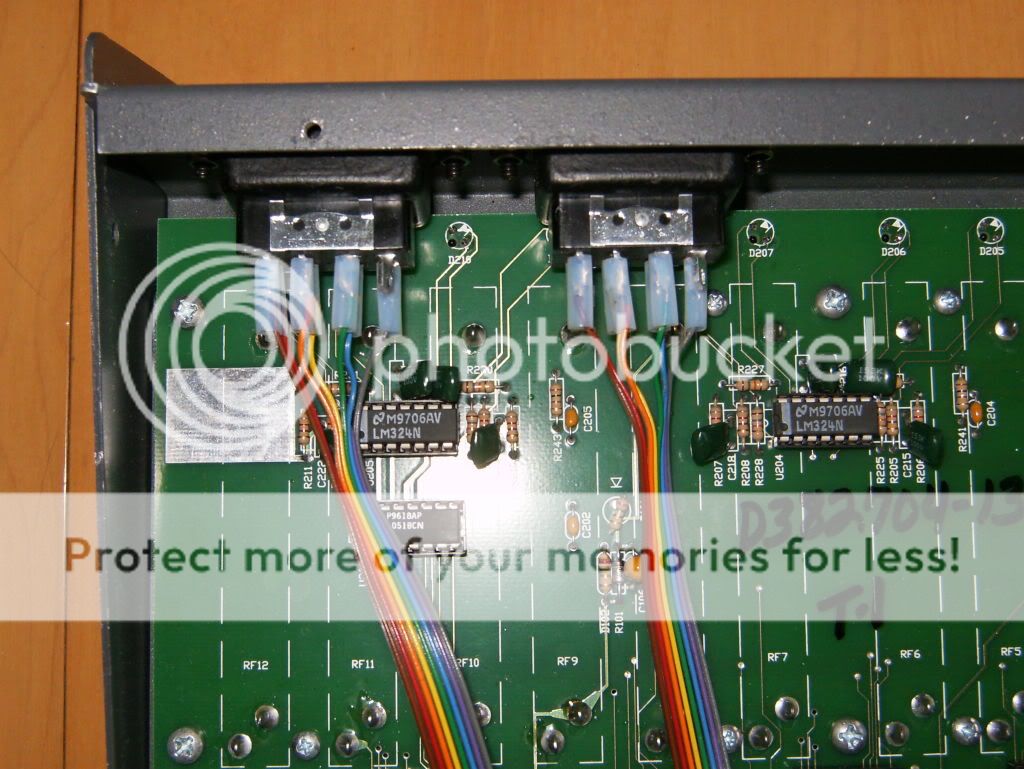
console pots are read via U503A (LM324). So if the processor wasn't getting anything from U503A it would look like all the console pots were not responsive, which was one of the major symptom for this console. Checking the output of pin 1 on U503 confirmed it: 0V straight line shown on a scope. And that was the first clue to what was the root problem.
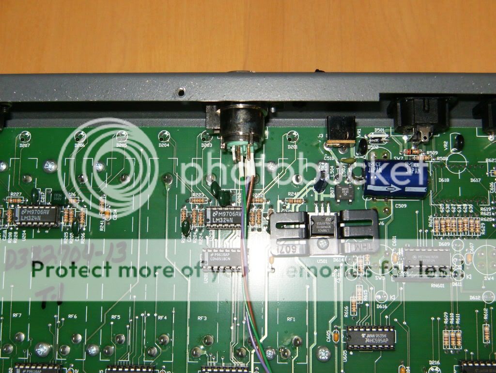
The block diagram also provides important key points to check first, and the power supply voltages shown are the very first thing to be checked. Here is where I found the next problem: There was no negative voltage on D504, which meant that any parts needing this negative voltage probably won't be working correctly. Well, U503 uses this negative voltage on pin 11. This is the 2nd clue to the problem for this console.

You may be wondering how this console generates a negative voltage from a +12Vdc wall wart power pack. It's done with a charge pump. Shown below is a diagram showing the charge pump circuit in this console. Notice that it is made of 2 parts: an oscillator (at the top) and the actual charge pump (at the bottom). The oscillator creates a ~10KHz square wave (those 2 transistors are configured as a push pull output) which drives the input capacitor of the charge pump. The 2 diodes and remaining capacitors charge up alternately to create the needed negative voltage.

1622511272648.png


First thing I did was put my scope probe on the output of that oscillator and found a very diminished square wave. No wonder the charge pump wasn't working. First thing I suspected was C507( 22uF tantalum capacitor not 47uF) was shorted. [NOTE: C511 is 47uF and C507 is 22uF]. So I cut C507 out of the circuit and saw that the output of the oscillator was restored! As I patted myself on the back, I replaced the C507 with a new cap, applied 
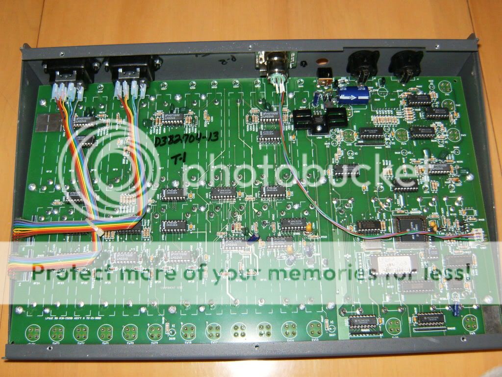
power and saw that the oscillator output was again diminished. This time I noticed Q201 getting warm. I said to myself must be C508 or C511 that were shorted! So I replaced them as well! Once again I applied power and found that the oscillator output was again diminished. What was going on??? At this point I kicked myself that I hadn't removed the load: U503 (LM324) and U502 (DAC0808), so I removed power and then removed the 2 IC's. When I again powered the board the charge pump was producing a negative voltage and Q201 wasn't even getting warm. Aha! One of those two IC's were bad!. To find the culprit I replaced U502 (DAC0808) and found that the charge pump still worked. OK, must be that LM324. I confirmed it when I replaced the suspect LM324 in the socket for U503 and the charge pump died. I borrowed an LM324 from a part of the console that wouldn't get used (the analog mux outputs) and put it in place of U503. When I again applied power to the board the console was working as expected! I mentally kicked myself in the butt for not doing the easy things first when troubleshooting a power supply: remove the load! Since every IC on this console board is in a socket that would have been an easy task. But no! I had to go the hard way!!! LoL ................ live and learn!

I hope my story was informative or at the very least amusing to some of the members of this forum. Once again I would like to thank Amiers for the assist! As a new member, I am very happy to be part of this very helpful community.
 

Users who are viewing this thread

Back