Control/Dimming Applied Electronics Dimmer Packs - Worth Saving?

Les

Well-Known Member
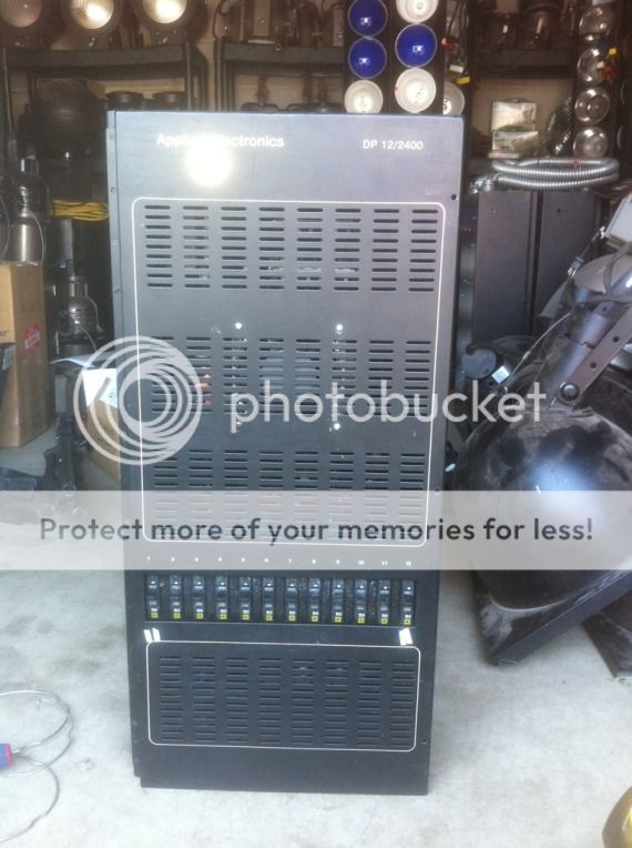
So, I had four Applied Electronics wall-mount packs given to me by a church who had purchased them used but never implemented them. Looking inside, I can tell that they were stored in a fairly dirty (and possibly damp) environment. Probably a non-climate controlled storage unit (not unlike the one I have them in now).

Things looks fairly decent and while old, they are are pretty simple so there's not a lot to go wrong. I did find one or two visibly damaged power cubes (thermal damage), but nothing completely terrible. I would like to take them somewhere and have them professionally assessed, but I thought I'd post a few pictures here before I spend any money. If all goes well, I'm hoping to loan them and a bunch of lights I have restored to an arts group in the Austin TX area who is going to be building a temporary space.

There are four of them, 2400x12ch, all in about the same condition.


I think it's safe to say they're analog.


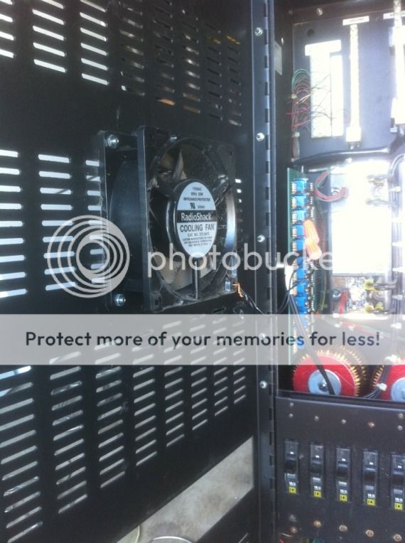
Overall, the inside is decent but needs a good cleaning. Someone installed this fan with some creative wiring. 100% sure that's not factory, but a field upgrade. They appear to have known what they were doing, for the most part, but it is a little messy and questionable:


It is connected to this breaker (bottom right) using what looks like 16 gauge lamp cord:


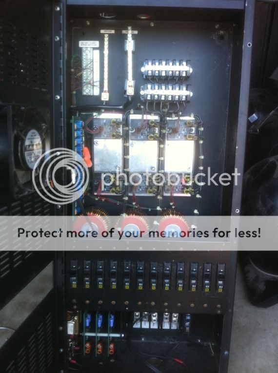
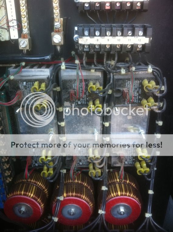
This unit has power cubes with no visible thermal stress, but they will still need to be checked. Very dirty:


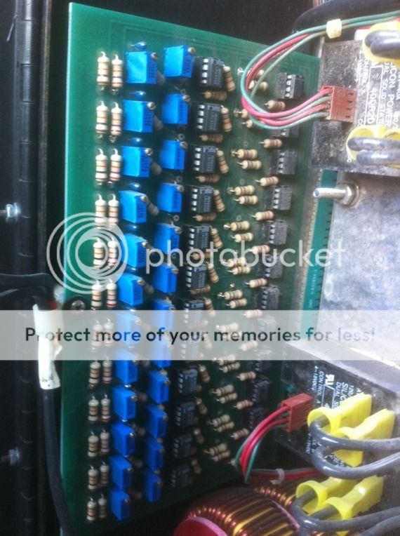
Some control circuitry. Also very dirty and "dry" looking.


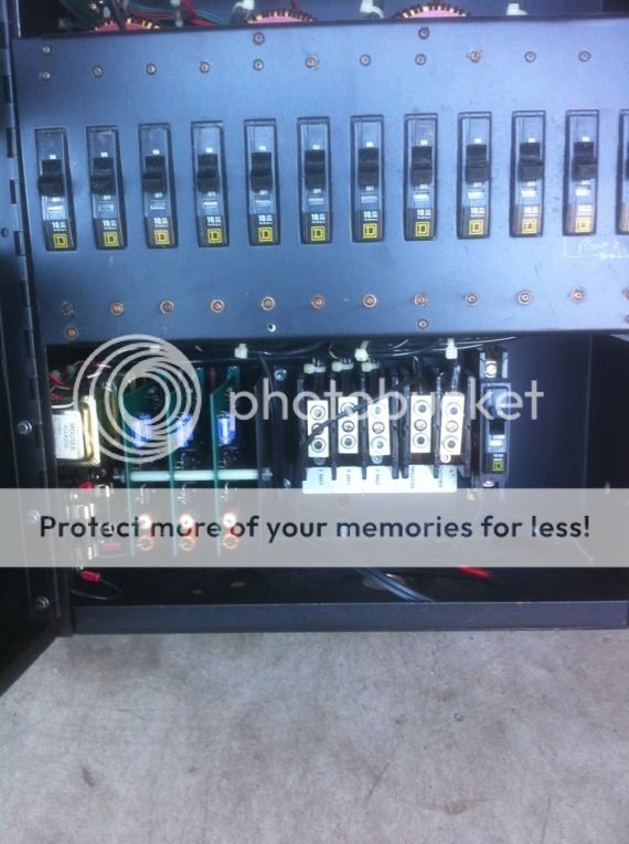
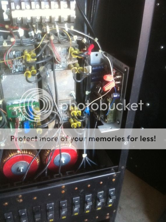
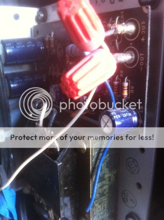
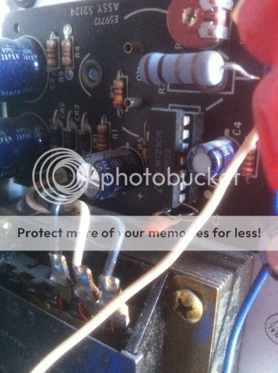
One of the packs has an extra set of components. The wire-nutted leads go directly to the terminal strip for the control circuitry. Would this be a DMX-Analog converter, or maybe an interface for a wall station? The bottom white and blue wires are cut -- the white wire is not spliced to the lead going to (or coming from) the SSR.

Notice that one of the power cubes is not like the others. Maybe a relay module or channel set up for a fluorescent/HID load?

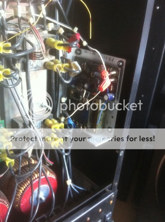
More shots of that "extra" board.


What do you guys think? It's 48 channels of 2400 watt dimming, so a lot of me wants to invest in these and make them right again (with professional, in-person help, of course).
 
Last edited:
The device in your last pictures is a regulated DC power supply. It was probably for powering wall stations. The thing look in decent condition and should be restorable. The question is whether the cost of 48 channels worth of DMX to analog converter, and the cost of wiring it to the wall packs would exceed the cost of buying a used, DMX capable rack.
 
I have repaired a number of old racks and put them back into service - they are often very robust as they were over designed. If you have the ability to repair them then why not do it? DMX converters can often be picked up used at a very reasonable price. You may be able to pick up a standalone board and mount it inside the rack. I have picked these up before for $150 each.
 
You may be able to pick up a standalone board and mount it inside the rack. I have picked these up before for $150 each.

Thanks for the advice, that reinforces what I was thinking of earlier, and that's just acquiring bare DMX-<12ch Analog boards and mounting them either inside or above each cabinet (inside would be better). Luckily, there is a lot of space inside these racks.

I've seen that Pathway and Northlight sell bare boards, even some with Merge features, which would be great since I have an analog architectural system that I'd like to integrate. I do need to find the the voltage range of these racks so as to make sure the slider stations are compatible as they are 0-10v. It might be a little complicated in the low voltage wiring, but for the amount of dimming vs little money spent (if I'm careful) it could really be worth it. I've seen DMX conversion boards on eBay as well (and for very cheap) but I don't know if I would go that route. Northlight's prices are very good (usually between $100 and $150 per board).

And thanks, FMEng for identifying that mystery board for me. It's good to know that it can just be removed if it's not needed for the system's "second life".
 
I have built quite a few systems using Northlight boards, and the build quality is excellent. If you call James at Northlight and tell him what you are doing, he will help you out a great deal. He will only sell you what you need and at pretty much the best prices for what is needed.
 
Just check the output voltage of that DC power supply board. Probably 10 to 12 volts, which would indicate a 0-10 vdc system. (Some overhead is needed on a passive system to make up for diode drop, so it will probably be above 10.) If the supply is above 12 volts, it may be a 0-12 system. Just a matter then of hot-wiring the rack and using a 10k ohm pot to double check a channel. Test the output of the pot when the dimmer tops out and see if it's 10 volts. One note, some architectural dimmers are trimmed to top out at 90% to extend the life of lamps used for house lights.
 
Thanks for all the help so far, guys. I brought one of the dimmers home so I can begin cleaning it up. A lot of it isn't dust from use, but dust/moisture residue from being stored. Thus, it needs to be wiped off rather than blown/sucked out.

A few questions in my mind at the moment-
What should I do about the fan? It was obviously added "after the fact", and I can now see that the breaker it's connected to was mounted in the enclosure using self-tapping screws (using the correct mounting bracket and all that). The mounting of the breaker appears safe, but I don't think it's the most efficient as it appears as though with this setup the fan would run continuously until the rack is powered down. Perhaps this would be more of a question for Applied Electronics, because surely the fan was added for some reason, but I don't believe even their new packs contain cooling fans. Maybe this was a way of combating environmental conditions such as being located in a non-air conditioned room? The breaker is tied in to the same terminals as the main feeders. If I did keep the fan, I'd prefer to find a way to have it thermostatically controlled.

Reading an AWG chart on the inside of the unit, they spelled tungsten "tungston". I thought Applied was better than that ;)

Would there be any use in applying dielectric grease on any of the connectors - namely at the power cube? I don't intend on messing with anything else unless it's signal related.
 
Last edited:
They use to sell little boards to throw between computer fans and power supplies to thermostatically control the fan. I'll see if I can't dig up something. They were all adjustable and had a thermometer built into the device.
 
They use to sell little boards to throw between computer fans and power supplies to thermostatically control the fan. I'll see if I can't dig up something. They were all adjustable and had a thermometer built into the device.

Thanks, I appreciate it!
 
one of the dimmers that I built using the Northlight DMX to 0-10 vdc, I installed fans and controlled them with the output of the Northlight board. I put steering diodes on all of the outputs as well as the leads running to the SSRs. I tied all of the diodes together on the opposite side from the board connections and fed that to an op-amp. One side of the opamp inputs was tied to a voltage divider to give about 3 volts as a reference. The other side to the diode array. The ouput of the opamp drove a transistor, that then drove a relay. The relay turned the fan on. In this way the fan sat idle until at least one of the channels from the 0-10 board was at 30% or higher. It worked really well, and the dimmers were on 24/7.
As an aside Northlight DMX to analog, can be ordered 0-5, 0-10, 0-12 and 0-15 volts DC. The older Electrol-Control dimmers were 0-15 volt input.
Another dimmer system that I built, I just installed a household thermostat in the dimmer cabinet and used it to turn the fans on.
 
I found this while searching through eBay.


Too bad it has that wall-wart, but installing a small 12v transformer in its place wouldn't be difficult. I'd probably keep the current 20a breaker they installed to protect the wiring leading to the transformer. Kinda 'spensive at $67, but a good deal if it helps protect six $100 SSR's.
 
Some FYI points I see in looking at the pictures:

1) White stuff is probably mold. (dust + moisture + time = mold)

2) The three little boards at the bottom are your X, Y, & Z ramp generators.

3) The longer circuit board with all the trim pots are your comparator circuits with low and high trim controls.

4) I see a lot of IC sockets. Although handy, over time they can cause problems if oxide builds up. Chips should be reseated.

5) Fan is probably not needed due to the low density construction but can serve to extend life of SSRs.
 
JD has given excellent advice. I often find with the ICs in the sockets that it is also useful to apply the gentlest touch of De-oxit using a cotton bud to the pins before reseating the IC. If the rack is 0 to 15 Vdc and you can only find 0 t0 10Vdc demux then you can easily build a simple OP Amp circuit to give you a gain of X1.5. If you retrim the rack for 0 to 10 Vdc it changes the dimming curve - may or may not be a problem.
 

Users who are viewing this thread

Back