turtle7896
Member
Haha, thanks again man.
Last edited:
Haha, thanks again man.
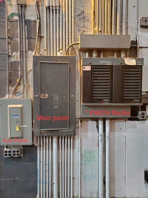
Here is what we are working with. There is another panel in the basement, but as it may be evident, we would probably not be able to work with it.There is no reason to search high and low for IG receptacles for LED stage lighting. Isolated Ground is for reducing hum/ground loops/noise in audio/video systems. It is unnecessary for lighting, and connecting lighting fixtures to IG receptacles will very likely compromise the integrity of your isolated ground system by introducing additional paths for ground loops into the audio system.
The best method would be to have an electrician disconnect a circuit from each lighting position, at the ENR24 rack, and feed those circuits instead from a standard panelboard. Since dimmer racks are usually located in electrical rooms with other panelboards, this is probably not a significant amount of work and an electrician could probably complete it within a day or two. Then you would have a constant-on circuit at each lighting position. If you needed 2 circuits instead of 1 at each lighting position, that's likely not that much more expensive so long as you have some spare capacity in another panelboard. By the time an electrician shows up on-site and starts performing the work, the relative cost of some extra conductors and circuit breakers is marginal once they're already there and set up to do the work.
If this is a theatre covered by NEC article 520, portable cord wiring is considered "portable" not "temporary" which is specifically covered by article 590 and generally refers to construction sites and the like. The requirements for cables in a theatre fall under 520.68 Conductors for Portables. There are also specific rules in 520.5(B) Wiring Methods--Portable Equipment.
ST
It may be in his other thread, but @turtle7896 is already using ColorSource Relays, it's just that they are being fed from his dimmed circuits now, which of course is not desirable.I would go a step further and connect an ETC ColorSource Relay at the end of your new conduit run, and then connect your fixtures to that. Then you don't have to run your fixture's power supplies 24/7 even when "off" (a practice which makes my eye twitch). The CS relay has DMX I/O so you loop your signal from that to each of your fixtures. It's bit of money but would be worth it in the long run.
Maybe this has been discussed earlier and I overlooked it in which case, carry on.
Colortran ENR24
Hey, so, 3 questions.1. Does anyone know when Colortran released the ENR24?2. Where can I get bulbs for Colortran spotlights?3. Good idea to mix an ETC Element (1), Colortran ENR24, and ETC ColorSource PAR lights together?Thanks for any help.(P.S. I am a highschooler and we are...www.controlbooth.com
It may be in his other thread, but @turtle7896 is already using ColorSource Relays, it's just that they are being fed from his dimmed circuits now, which of course is not desirable.
I hate to be the bearer of electrical bad tidings, but this discussion omits a serious issue: "fault current coordination".
I'm not sure if I would call it bad tidings. Any correction in the name of safety is a good one!I hate to be the bearer of electrical bad tidings, but this discussion omits a serious issue: "fault current coordination".
Dimmers with chokes provide inherent limitation of fault current. The design of the power system feeding a dimmer rack was no doubt based on a a specific fault current rating for that rack. It might have been 50,000 amps, or even 100,000 amps RMS symmetrical. This was based on the inherent "built-in" fault current limitation of dimmers with chokes.
Once you remove those chokes and use "breaker only" modules, your fault current rating for the entire rack falls to the rating of a single branch breaker itself, which might be as low as 5,000 amps RMS symmetrical. This could create an unsafe condition in the event of a fault.
So, what is the solution? "Constant Power" or relay modules must include fuses with sufficient interrupting capacity so that their use does not invalidate the original fault current rating of the rack.
Caveat emptor! Or put another way, TANSTAAFL!
ST
I hate to be the bearer of electrical bad tidings, but this discussion omits a serious issue: "fault current coordination".
Dimmers with chokes provide inherent limitation of fault current. The design of the power system feeding a dimmer rack was no doubt based on a a specific fault current rating for that rack. It might have been 50,000 amps, or even 100,000 amps RMS symmetrical. This was based on the inherent "built-in" fault current limitation of dimmers with chokes.
Once you remove those chokes and use "breaker only" modules, your fault current rating for the entire rack falls to the rating of a single branch breaker itself, which might be as low as 5,000 amps RMS symmetrical. This could create an unsafe condition in the event of a fault.
So, what is the solution? "Constant Power" or relay modules must include fuses with sufficient interrupting capacity so that their use does not invalidate the original fault current rating of the rack.
Caveat emptor! Or put another way, TANSTAAFL!
ST
Indeed, @STEVETERRY; it's not clear from your posting whether that change in rating comes from replacing *all*, *some*, or *only one* dimmer with a relay/passthrough module.Can we assume though that a swap of maybe 1 module, with the rest remaining as dimmers, might not be a problem ? I can certainly see an issue if the entire rack got swapped.
The reduction in rack fault current rating only needs ONE module to be changed to a choke-less implementation. In such a case, the WHOLE RACK's fault current rating is reduced.Indeed, @STEVETERRY; it's not clear from your posting whether that change in rating comes from replacing *all*, *some*, or *only one* dimmer with a relay/passthrough module.
NO. Please see my post to Jay Ashworth.Can we assume though that a swap of maybe 1 module, with the rest remaining as dimmers, might not be a problem ? I can certainly see an issue if the entire rack got swapped.
ETC Sensor CC15 and CC20 constant current modules have fuses. From their data sheet:
We use essential cookies to make this site work, and optional cookies to enhance your experience.