Control/Dimming Can you identify this dimmer?

IdlePhase

Member
Hello everyone, I am a member of my highschool's tech crew and we recently discovered this rack-mounted device. For events not hosted in our auditorium we would just use PAR Cans with gels all controlled by power bars. This seemed to offer a fantastic solution but it broke shortly after we discovered it.

Do you know what this is?
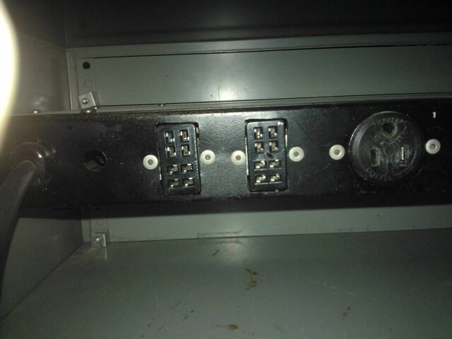
What are the ports on the back for (except NEMAs)?
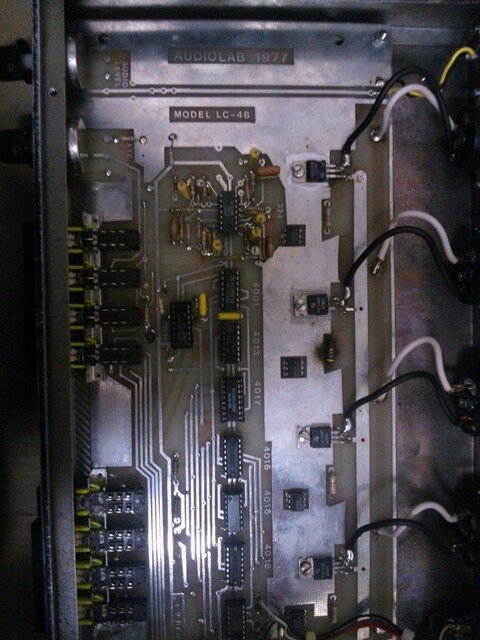
How should we repair it?

Here is some information:
  • We think it was used to control PAR Cans for our school's dances back in the 90s
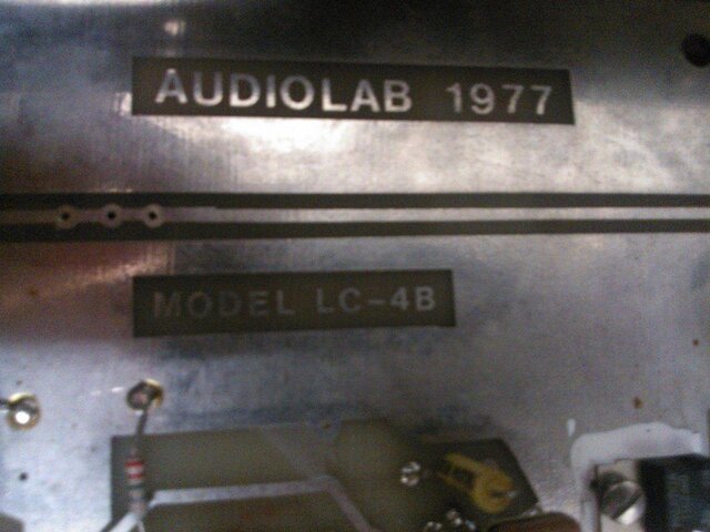
  • The tape on top of the rack says "Fixed 1993" (However not sure what it is referring to)
  • The table top rack is not important
  • When strobe mode is selected, the 4 outputs on the back create a variety of chase effects (direction changed by the A, L, R, S buttons)
  • VR 3 Intensity controls the output level, VR 2 OSC controls the chase frequency
  • The port on the far right, seen from the back of the device, seems to fit an RCA connector
  • The AC switch turns it on. However after some testing of the device, this became increasingly loose and now can be pulled out and falls back in. The device no longer turns on.
Please see the full album

600097_470602926315683_1875400997_n.jpg
I appreciate any knowledge of this device you share.
 

Attachments

  • zJ9BXzY.jpg
    zJ9BXzY.jpg
    66.2 KB · Views: 403
Looks like an old DJ grade dimmer relay pack, probably late 70s-early 80s vintage. Those square muti pin connectors are called Cinch-Jones connectors, probably for an external controller. I bet one is in, the other is parallel out for another pack. Your gonna need that controller to make it do much of anything else. It appears to have a sound activated mode, thats probably what the RCA connector was used for. Cant really tell ya to much else without seeing the guts. As for fixing it, its probably all discrete components inside, anybody familiar with electronics should be able to repair it for you.


As for the HAmmond sticker. the Hammond comapny made electronic organs back in the day. These were popular in schools, churches, anyplace witha theatre or stage. Thats probably one of their equipment racks that would have originaly housed amplifiers and other equipment for the organ. Doubt it has anything to do with your pack.
 
Last edited by a moderator:
Looks to me more like what a DJ might refer to as a Chaser. A chaser is basically a shoe-box dimmer with built in programs that chase the lights in different patterns.
The port that looks like an RCA connector probably is one. Most of the older chase boxes didn't have built in mics like the ones today so they took a line level out of the DJ's mixer (as far as I know). I wouldn't connect anything to the RCA until you make sure it's not gonna send mains power through. It though looks pretty old and broken down.
As far as those 2 ports on the back, I would imagine they go to some sort of analog dimmer controller that ran off of a 0-10v system.
If you just want something to run some Par cans off of, I'd suggest just buying a couple new Shoe-box dimmers. Just make sure they support the wattage of whatever pars that are being plugged into em.
 
It looks to be a 4 circuit chase effect controller. With it being a single U case, I can't see it being rated for that much power.

From looking at the front, one of the knobs is labeled audio, from that I can infer that the thing that fits an RCA plug is an audio feed to make the lights dance to the music.

The two rectangular plugs on the back are to connect into a lighting system using analog control signals.


As far as fixing it is concerned, it probably isn't worth it. From the looks of it it dates to late-70s early-80s. Given that you don't have any info on it and it was probably nearly obsolete when it was fixed in 1993. In order to integrate it into a modern lighting system you'ed have to get an analog to DMX converter which costs a bit. Judging by the Edidon plugs on the back, I'd say it was intended more for the DJ market.
 
Looks like an old DJ grade dimmer relay pack, probably late 70s-early 80s vintage. Those square muti pin connectors are called Cinch Jones connectors, probably for an external controller. I bet one is in, the other is parallel out for another pack. Your gonna need that controller to make it do much of anything else. It appears to have a sound activated mode, thats probably what the RCA connector was used for. Cant really tell ya to much else without seeing the guts. As for fixing it, its probably all discrete components inside, anybody familiar with electronics should be able to repair it for you.


As for the HAmmond sticker. the Hammond comapny made electronic organs back in the day. Thesow guys the more I look at e were popular in schools, churches, anyplace witha theatre or stage. Thats probably one of their equipment racks that would have originaly housed amplifiers and other equipment for the organ. Doubt it has anything to do with your pack.

He doesn't necessarily need one of the old control boards they make a DMX to analog converter for that. I've got one sitting out in the garage. The college I went to had just replaced a system with analog dimmers controlled by a DMX board and they were tossing stuff.

You know the more I look at the way its labeled on the front, the fact its probably got discreet componnts given its apparent age, and that there seems to be no identifying marks as to manufacturer I'm thinking it may have been a Homemade unit.

While im sure a A to D converter could be utilized, the pin out and proper control voltages would need to be determined first. I bet anything that the other half of that system is sitting in a moldering cardboard box somewhere in the OP's school. Or maybe its at the bottom of landfill wondering where its buddy has been for the last 20 years......

What I find interesting is that it apparently has the ability to vary intensity for each channel. I guess triacs and related technologies have been around for a while, I just didn't think that they made their way into lower end equipment such as this, much less be compressed into one rackspace. I bet it wont take more than 200 watts per channel.\

I know a guy thats been doing mobile DJ work for almost 40 years. He has a bunch of old turntables and lighting and stuff like that, and can tell you about almost any old piece of DJ gear. Ill show him this thread and see if he knows anything. Back then, allot of DJ lighting gear was homemade or made by small companies, as their was a much smaller market for it. I do know that some of chauvets early offerings were pretty basic and unmarked, it could even be made by them.
 
Last edited:
This week I'll remove it from the rack. Would it be helpful to open it up to take some photos? (I am not trained so I wouldn't attempt repair) I will also make an effort to look around in some of our long forgotten storage areas to see if there are any analog controllers using the cinch-jones connectors. Thank you for the feedback so far!
 
... Would it be helpful to open it up to take some photos? ...
Sure, once disconnected from all power sources, open it up. Hopefully there will be a manufacturer's name on the PC board.* I suspect a small Canadian company that went out of business in the mid-80s, when the disco era ended.

It's really a neat little unit that any decent electronics tech should be able to repair, but it's obsolete, probably unsafe (no OCPD on input or outputs), and there are better products available today.

It sounds like you've figured most things out. Here's some educated guesses...
VR1 AUDIO ...is audio input sensitivity VR=variable
VR2 OSC ...is oscillate (chase) speed

FILTer: LP/HP ...low pass/high pass, whether the unit uses high or low audio frequencies as a trigger
OSC: VR1/VR2 ...whether the chase follows the audio beat or speed set with rotary pot 2
INT: VR1/VR3 ...whether the intensity follows the audio volume or level set with rotary pot 3
MODE: STROBE/INT ...whether the chases or just fades

DIRECTION:
A ...not sure, probably Alternate (what Express/ion users would call bounce)
L ...left
R ...right
S ...this one has me stumped, perhaps Solid or Sync'ed--all four channels do the same thing?

VR3 INTENSITY ...is dimmer level of all four channels

I have no idea why there are two Cinch-Jones 8pin "Remote" connectors and why there are associated switches on the front panel.

EDIT: Another has posited:
Maybe:
A All (everything on)
L Left
R Right
S Stepped ( 1&2 / 3&4 alternate.)

*and maybe we'll find the unit at http://vintagenightclublighting.blogspot.com/ .
 
Last edited:
VR1 AUDIO ...is audio input sensitivity VR=variable
VR2 OSC ...is oscillate (chase) speed

FILTer: LP/HP ...low pass/high pass, whether the unit uses high or low audio frequencies as a trigger
OSC: VR1/VR2 ...whether the chase follows the audio beat or speed set with rotary pot 2
INT: VR1/VR3 ...whether the intensity follows the audio volume or level set with rotary pot 3
MODE: STROBE/INT ...whether the chases or just fades
Thank you for this explanation. If we can bring this device back to life, we will know how to use it. I will have photos of the inside to post in a few hours. I was unable to find any controllers in storage with cinch-jones connectors,but I will keep looking. What additional functionality would exist if there is a controller which can connect to this?
 
... What additional functionality would exist if there is a controller which can connect to this?
I suspect likely no additional functionality, only the convenience of a control panel that duplicates all/some of the front panel controls in a more desktop-friendly package.

If you do get it functioning, be mindful of the total capacity. Since it probably has a NEMA 5-15P on it, it's limited to 1800W total of all four channels. That's only 450W per channel. Lack of OCPD and Listed, by NRTL would be reason enough to NOT use it, in my book at least.
.

This mythical controller might allow individual channel intensity and stuff like that, my simple mind has a hard time understanding why they would go through all the trouble of adding triacs and associated circuitry for each channel for just a chaser pack without also including some way to individually control each channel. 8 pin connector, that's enough for individual control for each channel plus ground leaving 3 for other stuff.
 
.. Lack of OCPD and Listed, by NRTL would be reason enough to NOT use it, in my book at least.
.

8827-can-you-identify-dimmer-kalnyrlh.jpg


8828-can-you-identify-dimmer-piosedwh.jpg


Here is the album of photos from when we opened it today. I do see one fuse, but another slot where it looks like a second should go. The model is also listed. I'd need to arrange with my school to have it repaired, so this leaves two questions for me: what type of person should I contact to have it looked at, and how much do you think it would cost for someone to mend some of the wiring.
 

Attachments

  • xRZqgjlh.jpg
    xRZqgjlh.jpg
    110.4 KB · Views: 164
  • KALnYRLh.jpg
    KALnYRLh.jpg
    137.2 KB · Views: 310
  • piOSEdwh.jpg
    piOSEdwh.jpg
    136.3 KB · Views: 320
Last edited by a moderator:
Here is the album of photos from when we opened it today. I do see one fuse, but another slot where it looks like a second should go. The model is also listed. I'd need to arrange with my school to have it repaired, so this leaves two questions for me: what type of person should I contact to have it looked at, and how much do you think it would cost for someone to mend some of the wiring.

Wow, serious flashbacks man!
Good old 555 chip as the main timer/osc, 4000 series early cmos flip/flops and decade counters, MO3010 photo-triac isolators driving a 470 ohm resistor from the gate to MT2 on the triacs..... no filter chokes... discrete bridge rectifier, probably a 7812 or 7815 to220 regulator, 324 quad op-amp... VERY 1977 !!!

So what type of problem is it having? If channels are stuck on, then you have blown triacs (flat little things with the white gunk on them.) Can't make out the part number, but I bet the old 511-BTA24-600BW would work! Almost all the parts in there are still available today.
 
Last edited:
I see at least one resister that looks like it was shorted out, with charring. Also that second fuse holder looks like someone soldered a jumper in it, that would HAVE to be replaced with an actual fuse before EVER applying power again! (IMHO) After those I would see if you can get it to turn on again and see what (if anything) it does. If you have channels sticking look at the triacs. If you have unexpected behavior (strobing when supposed to be solid ect.) then look at the chips. Each of those look like standard chips that can be picked up online easily.

As for repair I'm sure any decent electronics person could repair it. Check around for local technical/vocational schools that have a Micro Electronics class and see if they will take a look at it. Not only can you get it fixed, it's a learning experience for them. And a lot of times they will do it for free as long as you don't have a hard time frame.
 
Wow, serious flashbacks man!

I am glad you enjoy. This is from way before my time so I am not familiar at all with its components; However, I have great respect for those who made it. The unit was working fine, we just had little clue as to how to operate it. During the testing, we were simply unable to turn it back on after turning it off. If there are abnormalities with the different controls, I wouldn't know, since I have no base line of its performance with which to isolate any problems.

Check around for local technical/vocational schools that have a Micro Electronics class and see if they will take a look at it. Not only can you get it fixed, it's a learning experience for them. And a lot of times they will do it for free as long as you don't have a hard time frame.
That is a nice possibility that I didn't think of, there are 2 universities and a college in my city. I'll contact them to see if they have any programs which would be able to help.
 
Last edited:
The "bypassed" fuse holder looks to have been a production change. In the original design, the fuse was on the neutral leg. It appears to have been moved to the hot leg and relocated off the PCB. All the connections in the area appear to be the same age, and I doubt the consumer would have had any desire to make the change.

Burnt area shows that one of the triacs went bad at some point (prob open MT2) burning the resistor, and that the unit was serviced.
 

Users who are viewing this thread

Back