Electrical multi-phase coupling ?

SteveB

Well-Known Member
Wouldn't know what else to call this, but somebody else can tell me if this is kosher and or if they've seen something like this in other locations.

My building is U shaped, with 2 theaters in the right arm (Gershwin), 2 in the left arm (Whitman), 2 of those 4 theaters being in the basements. The dock and assorted shop, dressing rooms, costume shop facilities are clustered vertically in the base of the U.

For as long as I have worked in this building, I've known that there are 2 electrical services, one per arm, with the “dock” section powered off the right arm. As far as I was aware (31 years now) the services were completely independent of each other, 2 building service entrance panels (actually new ones installed in '81), 2 electrical meters, etc... Each service is from an underground transformer vault containing dual transformers, one per building, located about 50 ft outside our loading dock. They are on college property, but maintained and serviced by Con-Ed - the utility company. I assume the transformers are fed from one main service coming underground in the street.

My assumption about 2 completely separate services, one per building, no connection between, got tossed on it's head today.

Turned out that some electrical panels (3) in our left arm theater box office (way down at the tip of the left arm), which I KNOW has panel breakers in the left arm building service entrance panel, were ALSO fed, simultaneously, from the other arm of the facility and it's supposedly separate electrical service. The panel dual fed is mostly all stairwells, lobbies, exit lights (as well as other crap added over the decades), etc.... so the theory, as far as we can guess for a 1955 build, was that this dual service was to provide an alternative power source in the event of a left arm building loss-of-power.

The dual feed was not accomplished using any sort of relay system (which I assume was not available in '55 ?), instead the panel feeders from one buildings service were simply tapped into the panel on top of the 2nd buildings service wires. The panels, as BTW are approx. 60 to 80 amp rated panels.

Huh ?, was all I could ask/state. I didn't know you could do that !.

Besides voltage drop issues related to cable lengths, not to mention how and what exactly do the 2 separate electrical meters measure ?, has anybody ever heard or seen a setup like this.

Curious in Brooklyn.
 
Last edited:
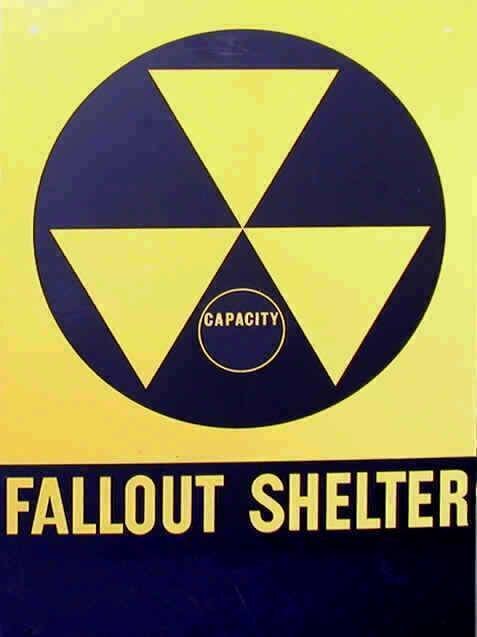
Just taking a shot in the dark here, but was your building ever used as a fallout shelter? Somewhere I remember reading that buildings used as fallout shelters sometimes had 2 different sources of power, just in case one went down.

shelter.jpg
 
Not really sure if I am following correctly (I actually had to draw it out LOL) but I think I have it. The "shared" panel is connected to the service panel 1 and 2 through sub panel feeder, correct? If so are they connected with a phase coming from each service or are they just 2 feed wired connected to a single main lug?

If the former I guess that could work, though I would think there would be some code issues (I am self taught and not up to date on codes so don't take my suggestions for gospel. Get a licensed electrician in to take a look at it!) I don't see a problem with it. If it is the latter then I would say to disconnect it immediatly and have it redone! I can think of a few issues where a surge on one side could feed into the other service, and possibly all the way back to the transformers and blow them also.

I could possibly see if the shared panel is an emergency panel (where you want that panel to have power at all times, for emergency lighting and such) where you could want the redundancy but I know there are better ways to hook it up to begin with.
 
My building is similar. National grid has 4 feeds to the plaza. All are connected via transfer switches. Most of my building is on one feed. Emergency systems are bonded on 2 other feeds.

Sent from my Galaxy Nexus using Tapatalk
 
Just taking a shot in the dark here, but was your building ever used as a fallout shelter? Somewhere I remember reading that buildings used as fallout shelters sometimes had 2 different sources of power, just in case one went down.

View attachment 6236

Have heard about this as well. Are either of the transformers in hardened vaults? I would assume the one that feeds multiple buildings... However, thats kind of a silly assumption because the EMP would knock down the generation plant, if the concussion didnt level the place or the fireball incinerate it. Are your gennies hooked up to that feed?
 
Not really sure if I am following correctly (I actually had to draw it out LOL) but I think I have it. The "shared" panel is connected to the service panel 1 and 2 through sub panel feeder, correct? If so are they connected with a phase coming from each service or are they just 2 feed wired connected to a single main lug?

If the former I guess that could work, though I would think there would be some code issues (I am self taught and not up to date on codes so don't take my suggestions for gospel. Get a licensed electrician in to take a look at it!) I don't see a problem with it. If it is the latter then I would say to disconnect it immediatly and have it redone! I can think of a few issues where a surge on one side could feed into the other service, and possibly all the way back to the transformers and blow them also.

I could possibly see if the shared panel is an emergency panel (where you want that panel to have power at all times, for emergency lighting and such) where you could want the redundancy but I know there are better ways to hook it up to begin with.

Attached drawing to better describe.

This has existed as new construction done in 1955. Nobody's touched it except to add emergency generated stuff (not shown as not relevant to the OP, but which may get used). MANY electricians and the engineer are currently shaking their collective heads tonight, myself included.

@ Footer. No transfer panels, just feeders from 2 separate building services tapped to feed 3 panels from both services concurrently. 1955 remember, so I suspect there were no available automated relay systems at the time that could sense loss of one building and transfer, which is how it's done today.

@ DrPinto, yes these were fallout shelters, so probably that had something to do with it, assuming there was still a grid to provide power, Yuk, Yuk.

@ Shiben. No hardened vault. Just a couple of steel grates covering (that are buckled and have safety cones around them for the past 4 mos.). There's one semi-functional generator for both buildings and whose use and distribution system will come into play as we separate these feeders.

So it will get changed. I won't use the term fixed as I'm not sure it's broke. Old and probably long past code compliant, but it HAS functioned and not burned the building down, for 56 years now. Well, I THINK it functioned.

What trouble me is the use of current from 2 transformers at the same time and attendant issues of longer cable runs from the Gershwin side, as well as what were the electrical meters metering when you had potential back flow of current ? I.E. We had 2 sources of power feeding one set of fixtures at the same time. Both being metered and charged for separately. Do they owe us money for that - Just Kidding.

Just a really odd ball setup.

EDIT: And a scary thought. The lighting panels are labeled EM1, EM2 and EM6, so dead give-away that they were originally designated for emergency use. In each of the original service entrances there are main breakers labeled the same, just in 2 different panels in 2 different (but attached) buildings. So you are an electrician adding something to a panel (or swapping the entire panel) and you shut it down in that panels main service. But you didn't as it feeds from the 2nd building as well. Hopefully you were not having a lets-be-stupid day and assumed once you tripped the breaker the power was off and double checked and metered. NOWHERE on any of the 3 panels were there labels "DUAL FED FROM WHITMAN AND GERSHWIN, M1 & M2 PANELS" or any such warning.
 

Attachments

  • WW Dual Feed Layout.pdf
    73.6 KB · Views: 227
Last edited:
Attached drawing to better describe.

This has existed as new construction done in 1955. Nobody's touched it except to add emergency generated stuff (not shown as not relevant to the OP, but which may get used). MANY electricians and the engineer are currently shaking their collective heads tonight, myself included.

@ Footer. No transfer panels, just feeders from 2 separate building services tapped to feed 3 panels from both services concurrently. 1955 remember, so I suspect there were no available automated relay systems at the time that could sense loss of one building and transfer, which is how it's done today.

@ DrPinto, yes these were fallout shelters, so probably that had something to do with it, assuming there was still a grid to provide power, Yuk, Yuk.

@ Shiben. No hardened vault. Just a couple of steel grates covering (that are buckled and have safety cones around them for the past 4 mos.). There's one semi-functional generator for both buildings and whose use and distribution system will come into play as we separate these feeders.

So it will get changed. I won't use the term fixed as I'm not sure it's broke. Old and probably long past code compliant, but it HAS functioned and not burned the building down, for 56 years now. Well, I THINK it functioned.

What trouble me is the use of current from 2 transformers at the same time and attendant issues of longer cable runs from the Gershwin side, as well as what were the electrical meters metering when you had potential back flow of current ? I.E. We had 2 sources of power feeding one set of fixtures at the same time. Both being metered and charged for separately. Do they owe us money for that - Just Kidding.

Just a really odd ball setup.

There is hot-to-hot bonding at the panel from two different transformers? I must have read that wrong. Besides back-feed on lines thought to be switched off, any variance between the transformers would become billable energy usage. Be interesting to remove all loads but leave the breakers on and see if the meters are reading anything.
 
There is hot-to-hot bonding at the panel from two different transformers? I must have read that wrong. Besides back-feed on lines thought to be switched off, any variance between the transformers would become billable energy usage. Be interesting to remove all loads but leave the breakers on and see if the meters are reading anything.

I tried to answer with a simple "Yes". Forum wouldn't let me. Everything you said is correct.
 
Last edited:
I have seen this done in dc automotive wiring but never in AC. Theoretically if you have a light bulb that dual fed off of two 20amp circuits wouldn't that light bulb have to pull close to 40 amps to trip?
20a breaker ----
> light bulb
20a breaker ----
 
Attached drawing to better describe.

This has existed as new construction done in 1955. Nobody's touched it except to add emergency generated stuff (not shown as not relevant to the OP, but which may get used). MANY electricians and the engineer are currently shaking their collective heads tonight, myself included.

@ Footer. No transfer panels, just feeders from 2 separate building services tapped to feed 3 panels from both services concurrently. 1955 remember, so I suspect there were no available automated relay systems at the time that could sense loss of one building and transfer, which is how it's done today.

@ DrPinto, yes these were fallout shelters, so probably that had something to do with it, assuming there was still a grid to provide power, Yuk, Yuk.

@ Shiben. No hardened vault. Just a couple of steel grates covering (that are buckled and have safety cones around them for the past 4 mos.). There's one semi-functional generator for both buildings and whose use and distribution system will come into play as we separate these feeders.

So it will get changed. I won't use the term fixed as I'm not sure it's broke. Old and probably long past code compliant, but it HAS functioned and not burned the building down, for 56 years now. Well, I THINK it functioned.

What trouble me is the use of current from 2 transformers at the same time and attendant issues of longer cable runs from the Gershwin side, as well as what were the electrical meters metering when you had potential back flow of current ? I.E. We had 2 sources of power feeding one set of fixtures at the same time. Both being metered and charged for separately. Do they owe us money for that - Just Kidding.

Just a really odd ball setup.

EDIT: And a scary thought. The lighting panels are labeled EM1, EM2 and EM6, so dead give-away that they were originally designated for emergency use. In each of the original service entrances there are main breakers labeled the same, just in 2 different panels in 2 different (but attached) buildings. So you are an electrician adding something to a panel (or swapping the entire panel) and you shut it down in that panels main service. But you didn't as it feeds from the 2nd building as well. Hopefully you were not having a lets-be-stupid day and assumed once you tripped the breaker the power was off and double checked and metered. NOWHERE on any of the 3 panels were there labels "DUAL FED FROM WHITMAN AND GERSHWIN, M1 & M2 PANELS" or any such warning.

I don't like this at all.

1. There is a dangerous situation with a panel fed from two sources that is not marked as such.

2. The reality is that the two services are tied together at this bonding point. This means current can flow from one service to the other depending on wire length and impedance. This is a classic "backfeed" situation that is both dangerous and non-compliant.

I suggest you have this looked at by a qualified engineer and get it corrected.

ST
 
I think the safety issue has been well covered, so I'll not touch on that. From the metering aspect I doubt this is an issue. The setup basically has the main building transformers wired in parallel, with one branch having more impedance (due to cable length) than the other. The EM1, EM2, and EM6 panel loads will be split between the 2 building services. The split will not be even necessarily due to the longer cable length of one branch and the loading conditions of both main transformers. There could be some circulating current depending on the differences between the main transformers. This would be what I would be most curious about. If possible, an excellent experiment would be to kill all load in the 2 EM panels and then throw a clamp meter on the feed at the top of one of the EM panels and see if any load is circulating through the paralleled circuits. Any circulating load is going to be reactive (kVAr) and cause heating in the main transformers. It also reduces the usable load on the on the transformers since reactive current is still current even though it's not doing any real work.

I would also assume that the 2 main transformers must be paralleled on their primary sides. Otherwise you could have some distribution current flowing through your building, although that would be a relatively high impedance path since it would have the impedance of both transformers plus the impedance of both feeder circuits to the EM panels.

Overall, it's an odd situation and should be remedied with a proper transfer system if the redundancy is still needed.
 
No two transformers are wound exactly alike. The result is whatever difference there is will result in an idle current flowing between the two transformers. In this case, each transformer has a meter system on it, so whatever current is flowing will appear on both meters and you will get billed twice for power you did not even use!

As for the safety issues, the list is a long one! Not only is there a secondary back feed on the 120/208, there is also a step-up back feed on the 13kv primary. If indeed the primaries are hard wired together with one switch, then it is just a deadly situation. If there are separate primary switches, then it is suicidal. The potential exists for a utility worker to open a switch to one of the transformers, thinking it is disconnected, but the back feed would still leave 13kv on the "dead" transformer's Primary leads.

It's hard to imagine that this was actually done.
 
I don't like this at all.

1. There is a dangerous situation with a panel fed from two sources that is not marked as such.

2. The reality is that the two services are tied together at this bonding point. This means current can flow from one service to the other depending on wire length and impedance. This is a classic "backfeed" situation that is both dangerous and non-compliant.

I suggest you have this looked at by a qualified engineer and get it corrected.

ST

This has actually developed into a classic case of attempting to understand the original 1955 construction drawings, with no "as built" drawings, combined with additional work (15 years ago) to install a generator emergency system, again with no "as built" drawings from the contractor, combined with a whole lot of mis-labled drawings, panels and breakers.

Sigh.

Took the morning with engineers, GC's, college IBEW head, etc.... starting at 7 to get this figured out

So no feeds of panels from dual transformers.

The original plans however, do show 3 panels dual fed, but with those panels having only one set of feeders in the lugs and nobody could find a splice box where the so-called dual feeds from 2 transformers would have combined. We could not assume it was buried as access would have been required, so....

We then questioned the construction drawings. We then started using a real trace kit to generate trace signals from load back to breaker, which quickly determined that all was not as drawn.

The obvious clue became that 2 side-by-side panels had breakers labled for the same functions - I.E. "Mezz. Step Lights", or "Canopy North" in both panels. I could then recall that my original house lighting (audience chamber) setup (prior to '04, that's 2004 LOL) had alternating fixtures fed from 2 sources, with a set of panic contactors for one set of fixtures and a dimmed set of 2nd fixtures. Thus the logic of the building original electrical engineer became clear that he had dual fixtures fed from 2 sources and had routed power from the adjacent building for an alternative source and had it drawn wrong in the plans. Or the electricians told him he was crazy and changed the original design.

What's so odd was that neither the electrical contractor on the project nor the IBEW head elec for the college has trace kits (nor do they use them, preferring to follow conduit in the ceiling). I had to go dig mine out to generate signals that could be found in the panels, thus located the plan errors.

The cause of all this is a $75 million project for a new Perf. Arts Building. They are tearing down the "Right Arm" (Gershwin) or most of it, leaving the stage tower. Thus all utilities that routed thru the left arm (Whitman) is being isolated and separated. The electrical is giving them fits, as is fire alarms. They will soon discover (I'm betting) that the Whitman electrical service, in keeping with the original intent, has panels that fed alternating lighting in the building being torn down, thus they will need to find and isolate.

Fair to state that the project electrical engineer dropped the ball big time.
 
No two transformers are wound exactly alike. The result is whatever difference there is will result in an idle current flowing between the two transformers. In this case, each transformer has a meter system on it, so whatever current is flowing will appear on both meters and you will get billed twice for power you did not even use!

Yes, no two transformers are wound exactly alike or have the same impedance. The magnitude of the circulating current is governed by the impedance of the path between the transformer secondaries.

No, you will not be billed twice for the circulating current. By nature the circulating current is going out of one transformer and into the other, thereby creating a zero net effect when the metering data is combined. Further, the circulating current is reactive in nature. Most revenue metering systems bill based on kWh, not kVArh, therefore the circulating reactive current would not cause a double billing issue.

As to SteveB's situation, don't you just love renovation? I'm walking down a substation project next week where the client has already informed us that they have a wiring mess they want us to clean up. Only problem is the project is the replacement of several 345V circuit breakers in a generating station switchyard.
 
Last edited by a moderator:
No, you will not be billed twice for the circulating current. By nature the circulating current is going out of one transformer and into the other, thereby creating a zero net effect when the metering data is combined. Further, the circulating current is reactive in nature. Most revenue metering systems bill based on kWh, not kVArh, therefore the circulating reactive current would not cause a double billing issue.

I have yet to see a meter run backwards, and I tried! (Reversed the in and the out to see if reverse current flow would subtract.) I will qualify that statement by saying the meter was an older style motor meter. Basically there are two windings and a drag magnet. The first winding is a voltage winding, wired across the AC line. The second winding is a current winding. In home meters, it was a thick copper twist, in series with the load. (Commercial meters usually use a current meter loop toriad around each of the supply conductors.) In essence, current is what is measured. In the layout provided, each transformer is metered separately before the (now disproven) feeds get combined. As the meters read in "absolute" or positive values only, a resulting current flow would show as a positive usage on each of the two meters, even though this power was never used by the consumer. Therefore, it is safe to say the values would not cancel out. Mote point at this point anyway, but nice theory topic.

Of course, one could theorize that as long as the active customer load far exceeded the eddy bleed, the meter would not have to run in reverse, and that the eddy would only subtract from the higher positive value.
 
Last edited:
I have yet to see a meter run backwards, and I tried! (Reversed the in and the out to see if reverse current flow would subtract.) I will qualify that statement by saying the meter was an older style motor meter. Basically there are two windings and a drag magnet. The first winding is a voltage winding, wired across the AC line. The second winding is a current winding. In home meters, it was a thick copper twist, in series with the load. (Commercial meters usually use a current meter loop toriad around each of the supply conductors.) In essence, current is what is measured. In the layout provided, each transformer is metered separately before the (now disproven) feeds get combined. As the meters read in "absolute" or positive values only, a resulting current flow would show as a positive usage on each of the two meters, even though this power was never used by the consumer. Therefore, it is safe to say the values would not cancel out. Mote point at this point anyway, but nice theory topic.

Of course, one could theorize that as long as the active customer load far exceeded the eddy bleed, the meter would not have to run in reverse, and that the eddy would only subtract from the higher positive value.

I realized that I negated my initial thought of the circulating flow cancelling out. The circulating current is reactive, and possibly not measured by a simple revenue meter. We load test high voltage transformers in substations like this all the time. By paralleling the transformers on the primary and secondary sides and setting one of the transformers a tap above or below the other transformer, you can circulate vars between the transformers. It's a fairly odd arrangement in that you see current flowing through the secondary, but no real power (watts) since the current and voltage are 90 degrees out of phase.
 

Users who are viewing this thread

Back