
So this all started when my super and I were chatting about led dimming.
Normally, we use a repurposed 12V power supply from a server rack, and a little DMX decoder. It allows us to do 8 outputs of RGB and it works just fine.
We started discussing dimming white led tape however, and we stumbled on an idea.
"Hey...do you think we could do this with a dimmer?"
My super mentioned that you dim LED's by switching the power on and off really quickly(PWM), and that is fundamentally what an SCR does. So we gave it a shot.
We plugged a wall wart into a dimmer and plugged it into some tape a voila it sort of worked. There were some issues with curve however. The tape dimmed from 0-100 on dimmer output 0-30 it was smooth but didn't allow for much wiggle room. I mentioned that you can create your own curve and proportion in the ION to help, but he thought that he could mitigate the problem.
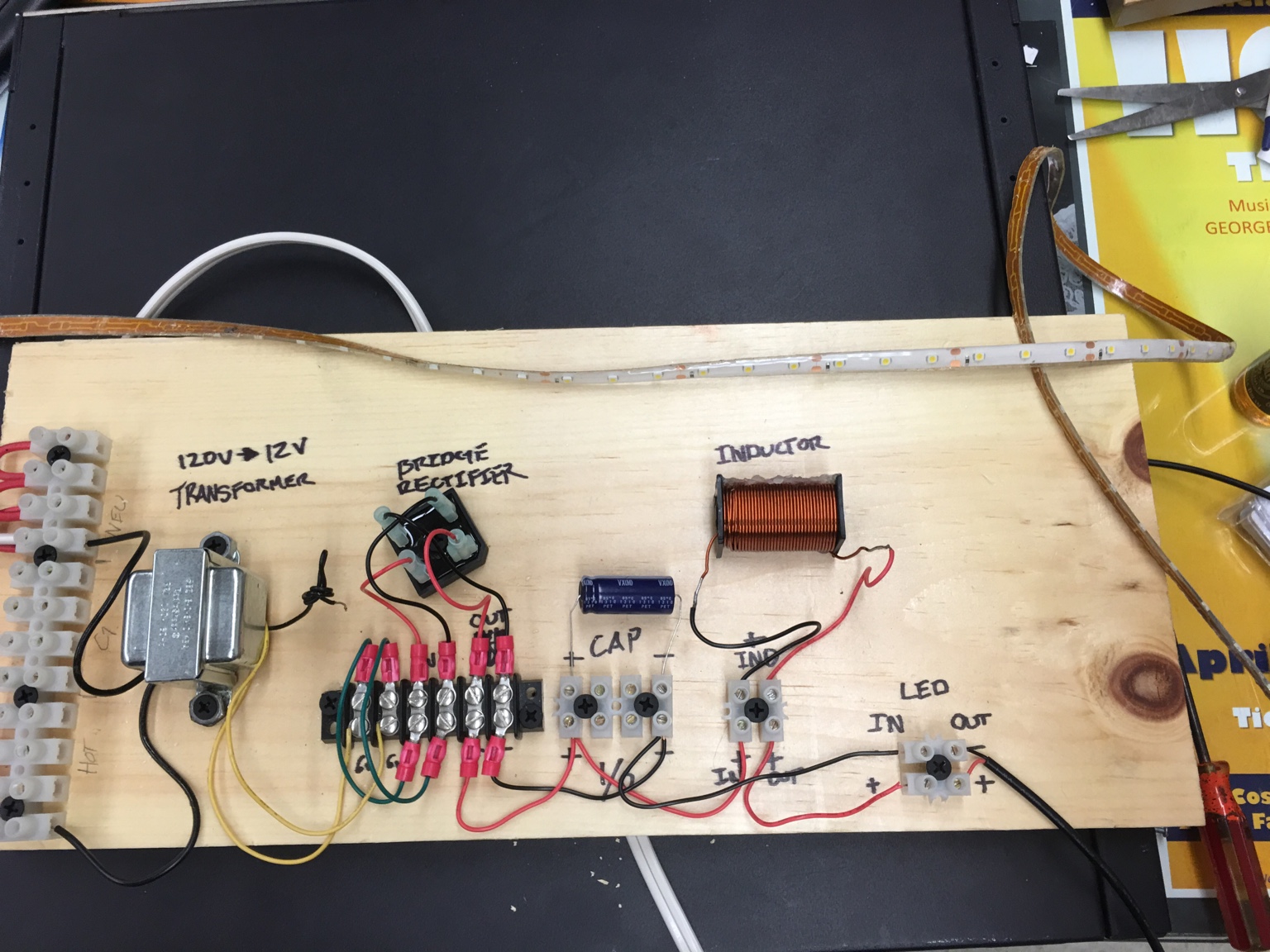
He decided to stop by RadioShack and pick up the components of a wall wart, minus the voltage regulator. He said that could be what was causing the problem. So I threw together the board in the photo.

120-12v transformer, bridge rectifier, capacitor, and inductor, out to the tape.
We prototyped it because it meant we could play around with different capacitors and inductors to see what happened.
It worked great. We hooked up our decrepit O-Scope.
What we saw was promising. Weird wonky sawtooth but overall it worked.
We left it dimmed for a while to see if we were burning anything up, and we weren't.
Between my super and I this seemed like a good solution.
Anybody else have any thoughts?
Sent from my iPhone using Tapatalk
Normally, we use a repurposed 12V power supply from a server rack, and a little DMX decoder. It allows us to do 8 outputs of RGB and it works just fine.
We started discussing dimming white led tape however, and we stumbled on an idea.
"Hey...do you think we could do this with a dimmer?"
My super mentioned that you dim LED's by switching the power on and off really quickly(PWM), and that is fundamentally what an SCR does. So we gave it a shot.
We plugged a wall wart into a dimmer and plugged it into some tape a voila it sort of worked. There were some issues with curve however. The tape dimmed from 0-100 on dimmer output 0-30 it was smooth but didn't allow for much wiggle room. I mentioned that you can create your own curve and proportion in the ION to help, but he thought that he could mitigate the problem.
He decided to stop by RadioShack and pick up the components of a wall wart, minus the voltage regulator. He said that could be what was causing the problem. So I threw together the board in the photo.
120-12v transformer, bridge rectifier, capacitor, and inductor, out to the tape.
We prototyped it because it meant we could play around with different capacitors and inductors to see what happened.
It worked great. We hooked up our decrepit O-Scope.

What we saw was promising. Weird wonky sawtooth but overall it worked.
We left it dimmed for a while to see if we were burning anything up, and we weren't.
Between my super and I this seemed like a good solution.
Anybody else have any thoughts?
Sent from my iPhone using Tapatalk