Where to begin installing a new lighting truss?

StradivariusBone

Custom Title
Premium Member
Fight Leukemia
So to preface, I don't intend on doing this work myself, but I've been tasked with doing some research to get started. Trying to update a church building with a new lighting position. The existing lights are hung via all thread through unistrut which appears to be bolted to the z channel purlins. Looks very much like commercial electric work to me, but I'm not sure how much weight we could theoretically place on those purlins. There are two I-beams that span the area where we would like to install the new lighting position, however the distance is just over 30' from beam to beam and of course there are HVAC ducts directly beneath both of the I-beams.

I've looked at various products designed to suspend from purlins and most seem to be rated for smaller things than truss and lighting. I haven't looked into the building plans yet to see if there's any information regarding the roof loading specs, but I've been pushing the powers that be that an engineer should pass their blessing to this endeavor before we begin to suspend anything more overhead. I guess I'm just wondering if it makes more sense to try and install beam clamps and points at an angle or if suspending from the purlins is more feasible. It would be simply enough to wrap chain on the purlins, but I have no reason to believe it wouldn't pull the buildng down with it.. I've attached some pictures to help illustrate what we're looking at. I've been talking with a commercial electrician that the church knows and trying to speak a language he understands. He too agrees that hanging anything needs to be well-thought out and planned for long term.


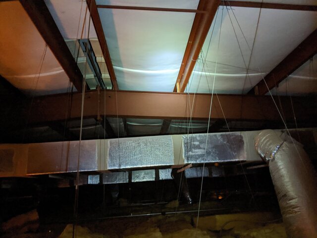
One of the I Beams. These run parallel to each other at about 30' apart.
img_20200305_192646-jpg.19609


Here's how the existing lighting batten is installed. Allthread down to the raceway with a pipe hung under. I'm assuming the unistrut is bolted, but it's hard to tell from the distance. I really hope it's not sheet metal screws.
IMG_20200305_192523.jpg
 

Attachments

  • IMG_20200305_192646.jpg
    IMG_20200305_192646.jpg
    388.5 KB · Views: 3,126
I've done quite a few projects with pre-engineered buildings. These are engineered as closely as possible to not an ounce of extra steel. And typically a structural engineer other than the full time employees of the pre-engineered building company either won't touch it or will add so much reinforcing it will astound you. Not a building type that learns well. ( How Buildings Learn - What Happens After They're Built by By Stewart Brand · 1995).

I assume truss is to be parallel with the frames, and perpendicular to the Z purlins? i think spreading a point load over several purlins might work but I would start by going back to building manufacturer.
 
Parallel the purlins unfortunately. That's why I was thinking a potential method would involve installing a point on the I-Beam rafters if anything. I don't know what kind of point loading you could throw over the span of a single purlin like that. I found a couple of load tables and none of them seem to indicate at a 30' span that you'd have a lot of wiggle room. Depending on the gauge and size (it's hard to tell since the drop ceiling is 8' below the roof) it could be as low as 40#/foot. We are thinking of a single truss running parallel to the edge of the performance area. It might need to be rethought into two separate trusses running at an angle to the stage edge (it's a thrust stage) to better utilize the building structure.
 
Looking at that allthread, I'm reminded of the KC Hyatt disaster. I was in that building in 2007, and remembered in time to look at the lobby...

Yeah, it makes me nervous. Allthread can be wicked strong, after all commercial electricians suspend building transformers with it all the time. I'm mostly concerned about how that unistrut is attached to the z purlin. All that's on it are a few PARs and two R2 moving heads. I won't let them install anything else before we address the structural stability of the building's bones.

This is an ignorant question, but that's how we learn. I understand bridles in concept and that the angles complicate loading with the multiplication factor affecting tension based on the angle of the bridle. So it doesn't seem possible to hang directly beneath the beams because of the HVAC ducts. Is there a bridling method that would involve hanging a leg from an angle off the beam, and then running a horizontal leg between the two angle legs to get a point above where the truss could be suspended?

Here's some bad MSPaint art:
1583880941228.png


And again, to reassure Jay ;), this is all hypothetical at the point. No one is buying or installing anything right now, and I personally won't be involved with this project unless a qualified person looks at the steel.
 
Parallel the purlins unfortunately. That's why I was thinking a potential method would involve installing a point on the I-Beam rafters if anything. I don't know what kind of point loading you could throw over the span of a single purlin like that. I found a couple of load tables and none of them seem to indicate at a 30' span that you'd have a lot of wiggle room. Depending on the gauge and size (it's hard to tell since the drop ceiling is 8' below the roof) it could be as low as 40#/foot. We are thinking of a single truss running parallel to the edge of the performance area. It might need to be rethought into two separate trusses running at an angle to the stage edge (it's a thrust stage) to better utilize the building structure.
@StradivariusBone Is it safe to assume snow loads on roofs are not a concern in your Florida neighborhood?
Toodleoo!
Ron (posting from where SNOW LOADS are a huge factor) Hebbard
 
Drawings do exist. I personally have not looked at them so I can't tell you specifics that could be gleaned from them. The building is about 25ish years of age from what I know.

Snow hasn't been a problem in these parts since the wooly mammoth moved on. Hurricanes keep bugging us though, but that's more of an issue with things going sideways instead of down.
 
Is this the part where I chime in "a licensed rigging engineer should *design* it, and sign off the print after installtion, before you put people under it, or your insuror will give birth to a porcupine, breech presentation"? :cool:
This isn't about the stage rigging, it's about building structure. And those aren't ibeams with known values - they're welded up beams sized and fabricated to just meet building code. Everything in the buildings structure is minimum. And engineers who design stage rigging usually exclude - in big print - building structure.

No way to put lighting at wall with its own columns to floor?
 
On the plus side, usually these type of buildings have model numbers and the manufacturer has assembled many of them. So unlike most regular buildings that have contractors, not manufacturers, these probably have oodles of real stress and weight calculations.
 
I've done quite a few projects with pre-engineered buildings. These are engineered as closely as possible to not an ounce of extra steel. And typically a structural engineer other than the full time employees of the pre-engineered building company either won't touch it or will add so much reinforcing it will astound you. Not a building type that learns well. ( How Buildings Learn - What Happens After They're Built by By Stewart Brand · 1995).

I assume truss is to be parallel with the frames, and perpendicular to the Z purlins? i think spreading a point load over several purlins might work but I would start by going back to building manufacturer.

I wonder if this is what is known as a “Butler Building”.

We have one on campus, erected temporarily about 20 years. It got repurposed for the film dept., when the building they inhabited was torn down. I was asked about a floor supported truss so they could install a lighting systems. They COULD NOT add any load to the existing roof beam system, was as Bill stated, no supplementak load capacity.
 
Yeah, it makes me nervous. Allthread can be wicked strong, after all commercial electricians suspend building transformers with it all the time. I'm mostly concerned about how that unistrut is attached to the z purlin. All that's on it are a few PARs and two R2 moving heads. I won't let them install anything else before we address the structural stability of the building's bones.

This is an ignorant question, but that's how we learn. I understand bridles in concept and that the angles complicate loading with the multiplication factor affecting tension based on the angle of the bridle. So it doesn't seem possible to hang directly beneath the beams because of the HVAC ducts. Is there a bridling method that would involve hanging a leg from an angle off the beam, and then running a horizontal leg between the two angle legs to get a point above where the truss could be suspended?

Here's some bad MSPaint art:
View attachment 19611

And again, to reassure Jay ;), this is all hypothetical at the point. No one is buying or installing anything right now, and I personally won't be involved with this project unless a qualified person looks at the steel.
What your drawing shows is what is known as a “H” bridle. Used in arena rigging, usually around scoreboards or other large obstructions. The down side to them is they “sway” back and forth when moving the truss, and you have to maintain equal load on both hoists or the truss will not remains level.

This is the type of project where there are so many variables and potential solutions that hiring an experienced rigger may be the most direct path to a viable design. and of course I’d be happy to talk to you about that off line.
 
No way to put lighting at wall with its own columns to floor?

Unfortunately, no. The original lighting battens were installed for a smaller stage, and I suspect they never anticipated anyone needing more than a few PAR cans. The room is wide and relatively shallow, but there's no where to install something like that since it is also multipurpose with removable chairs. The stage has since been expanded and the lighting positions are too far US to get most of it from an appropriate angle.

I'm starting to understand a bit more of what you're saying, Bill and Jay. Sorry, I was focusing too much on the "how" rather than the "if". My experience in hanging things comes from working in a building that was purpose-built for the hanging of things. I think this is good information to report back and I will try and dig up some information about the steel structure and if there was ever a thought to adding the strength to hang anything. As far as installation goes, this is looking to be closer to permanent as opposed to temporary. Or at least as permanent as such things can be. We do have a scissor lift for focusing and maintenance, so we are looking at dead hung.
 
Regarding the drawing, besides all the things Ethan said, the frames - the big beam every thirty feet - may not be good with lateral forces. In a normal steel frame building I'd rarely even consider it for the loads you are considering.

I wonder if spending for a thirty foot span and hanging plumb under frames is best possibility. Staying as far as possible from center of span - eave to ridge - would help. And spreading out point load over 4 or 5 feet of lower flange. You might find a local - sole proprietor - structural engineer who for not much - $100-200 - would give you a good opinion. Then decide if you want to go forward.

I missed it - dead hang or motors? Besides dead load of motors also design for impact is plus 10-20%.
 
Yeah, dead hang. Spanning 30' would involve moving a couple of trunk lines for the AC system to go directly under the I-beams hence why I was thinking of bridling, but that's a good point about lateral loading. Assuming the beam can even take the load, I'd wager it's probably not braced for sideloading to much if anything.
 
Well, you might get around duct. As a concept - two steel beams longer than duct is wide slipped over frame (you beam) and clipped to top flange; four hangers to two more similar beams parallel and under the two up top; and hang truss from those. Trapeeze
 
I review construction plans and structural calculations on my full time career fr building code compliance. I can assure you that a pre engineered building has no surplus capacity for hanging lighting rigs. At the most there may be a little capacity left out of the 5psf mechanical system allowance that should have been in the original design. However that may have been used by a sprinkler system, house lighting, electrical distribution system, etc. Have a registered structural engineer check it out but my experience is the answer will be no. You could design and construct a ground supported lighting grid but it will be very expensive and require massive footings to support the weight. Not a simple task.
 
Thanks for the book recommendation, Bill. Just picked up a slightly used copy online that arrived the other day and so far am engrossed.

IMG_20200319_080830.jpg


So far as what is being suspended currently, Joe is spot on. Lots of HVAC, sprinkler, drop ceiling, conduits, etc. I'm curious about the thought process behind the existing lighting. The hardware used (structural capabilities of the building aside) still looks so undersized for the task. But I guess lighting churches was different in the 90's.

I managed to find an older picture of the building in construction that I will share below. It looks like a pretty standard steel structure surrounded by wood frame ancillary buildings. I'm hoping to get time later today to see what if any plans still remain on site. Spoke to my boss and shared this thread with him and he has a friend who is a structural engineer who we will be communicating with in the future. Right now a majority of the focus is on getting the Sunday services online. So back to the back burner for a bit. I'm not sure what I'll do with myself without a 6:30am Sunday call for my side hustle!
 

Users who are viewing this thread

Back